
Installation Guide


R7284B,P,U,G ELECTRONIC OIL PRIMARY, ENVIRACOM™ ENABLED
3 69-2467—01
Location
1. Mount on a 4 in. by 4 in. junction box, directly on the
main burner, or inside the appliance cabinet. In
replacement applications, mount in the same
location as the old control. See Fig. 1. Make sure
the operating temperatures are within the ambient
temperature range (see Specifications section).
2. Before mounting the control, make line voltage con-
nections as shown in Fig. 2 through 10. Splice lines
with solderless connectors. Do not exceed load rat-
ings shown on the device label.
3. If necessary, use the control as a template to mark
and drill new mounting holes.
4. Mount the device using No. 6 screws (not included).
WIRING
WARNING
Electrical Shock Hazard.
Can cause severe injury, death or property
damage.
Disconnect power supply before beginning wiring
to prevent electrical shock or equipment damage.
More than one disconnect may be involved.
1. Make sure wiring complies with all local codes and
ordinances.
2. Check to make sure that line voltage wiring is
properly connected. Refer to oil primary label and
appliance wiring diagram for color codes.
3. After mounting make low voltage connections to the
screw terminals (see Fig. 2 through 10).
4. Strip leads 3/8 in. (10 mm) and insert under terminal
screw.
5. Connect thermostat leads to T-T (or 1, 2, 3 if
EnviraCOM™ is present), if required by installation.
Fig. 1. Mounting R7284 on junction box.
CHECKOUT
Start System
WARNING
Fire or Explosion Hazard.
Can cause severe injury, death or property
damage.
Make sure the combustion chamber is free of oil
and/or oil vapor before starting system.
1. Open hand valve in oil supply line.
2. Make sure system is powered. Check circuit
breaker or fuse and close system switch, if
provided.
3. Set thermostat to call for heat.
4. Make sure burner lights and operates until call for
heat ends. Note cad cell resistance while running.
5. Verify that burner turns off when thermostat call for
heat is satisfied.
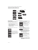
Fig. 2. R7284 terminals, connectors, LED, reset button
and DIP switch locations.
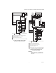
Fig. 3. R7284 wiring connections.
R7284
BURNER
M32085
M32146
DISPLAY
DISPLAY
ENVIRACOM
TERMINALS
THERMOSTAT
TERMINALS
ENVIRACOM
DIAGNOSTIC
PLUG
i BUTTON
DOWN
BUTTON
UP BUTTON
ENVIRACOM
TERMINALS
THERMOSTAT
TERMINALS
ENVIRACOM
DIAGNOSTIC
PLUG
i BUTTON
DOWN
BUTTON
UP BUTTON
M32178
CAD CELL CONNECTION
LINE VOLTAGE CONNECTIONS