
Installation Guide


69-0618—3
2
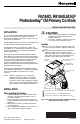
R4184D; R8184G,M,N,P Protectorelay
®
OIL PRIMARY CONTROLS
Table 1. Load relay contact ratings.
CAD
CELL LEADS
LINE
VOLTAGE LEADS
MOUNTING
SCREW HOLE
RED RESET
BUTTON
VENTILATION
SLOTS
4 x 4 JUNCTION
BOX
HOLE OR KNOCKOUT FOR
CAD CELL LEADS
LOW VOLTAGE
TERMINAL STRIP
1
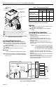
STRIP WIRES 3/8 in. (9.5 mm); INSERT FROM SIDE, ABOVE OR BELOW.
ATTACH WITH NO. 8 MOUNTING SCREWS (OBTAINED LOCALLY).
VENTILATION SLOTS ONLY AVAILABLE ON SELECT MODELS.
1
2
2
3
3
M1642C
Fig. 2. Wire and mount 150°F (66°C) maximum ambient
temperature oil primary control.
Line Voltage Wiring Connections
Wiring must comply with all local codes and ordinances.
쐃 Be sure all line voltage connections are in a wiring
enclosure such as a junction box or the appliance
wiring compartment.
쐇 Make the line voltage connections as shown in Fig. 3
through 9.
쐋 Splice the leads with solderless connectors.
IMPORTANT
Do not exceed the load ratings listed in Table 1.
쐏 Thread the line voltage cad cell leads through the
hole on the bottom of the low voltage terminal strip.
See Fig. 1 or 2.
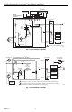
Fig. 3. Typical hookup for R4184D.
JUNCTION BOX
BLACK
ORANGE
WHITE
R2
SAFETY
SWITCH
M715A
POWER SUPPLY. PROVIDE DISCONNECT MEANS
AND OVERLOAD PROTECTION AS REQUIRED.
CAD
CELL
F
F
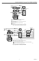
R4184D PROTECTORELAY CONTROL
SAFETY
SWITCH
HEATER
1K
TRIAC
BILATERAL
SWITCH
CAPACITOR
R1
1K2
1K1
1
1
IGNITION
LIMIT
THERMOSTAT
OIL VALVE
(OPTIONAL)
BURNER
MOTOR
L2
L1
(HOT)
®
Alarm Contact Rating: 25 VA at 24V, 50/60 Hz.
Mounting
쐃 If necessary, use the control as a template to mark
and drill new mounting holes.
쐇 Mount the control using no. 8 screws (obtained
locally).
Low Voltage Wiring Connections
After mounting, make low voltage connections to screw
terminals as follows:
• R4184D—connect the cad cell leads to the F-F
terminals. See Fig. 3.
• R8184G—connect the cad cell leads to the F-F
terminals and thermostat leads to the T-T terminals.
See Fig. 4 and 5.
• R8184M—connect the cad cell leads to the F-F
terminals and connect remaining low voltage wiring as
shown in Fig. 6.
NOTE: The Y and G terminals are
not
connected
to the internal circuitry of the R8184M. The
Y and G terminals are provided to simplify
the connections of the cooling equipment.
• R8184N—connect the cad cell leads to the F
1-
F
2
terminals and thermostat leads to the T
1
-T
2
terminals.
See Fig. 7.
• R8184P hydronic hookup. Connect the cad cell leads to
the F-F terminals. See Fig. 8.
• R8184P warm air hookup. Connect the card cell leads
to the F-F terminals and the thermostat leads to the
R-W terminals. See Fig. 9.
120 Vac 240 Vac
Model AFL ALR AFL ALR
R4184D;
R8184G,M,N
(45-second models)
7.4A 44.4A 3.7A 22.2A
R8184P (15-, 30-,
45-second models)
7.4A 44.4A NA NA
R8184G (15- and
30-second models)
10.0A 60.6A 5.0A 30.0A