
Product Overview

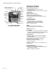
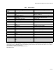
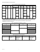
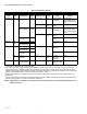

Table Of Contents

7800 SERIES RM7800E,G,L,M RELAY MODULE
66-2028—04 4
Table 2. Sequence timing for normal operation.
*
STANDBY and RUN can be an infinite time period.
**
PURGE will be determined by which ST7800A purge card is selected; 15 timings are available, from 2 seconds to 30 minutes.
a
The MFEP will be determined by which terminal is used, configuration jumper selected, or jumper wire added.
b
RM7800L1053: 10 seconds or intermittent.
Table 3. Combinations for terminals 8, 9, 10 and 21.
Table 4. Composition of each combination.
Device Initiate Standby Purge
Flame Establishing
Period
Run
Post
Purge
Timing
Interlock
Circuits
Firing
Rate
Circuit
Energy
Saving
Prepurge
Approval
Code
BodiesPilot Main
a
RM7800E 10 sec.
***
4 or 10
sec.
10 or 15
sec.
*
15 sec. Preignition,
Lockout,
High and
Low Fire
4-wire
modulating
Yes FM/IRI
Modulating
RM7800G 10, 15 sec.
or
intermittent
Preignition,
Running,
Low Fire
No UL/CSA
Modulating
RM7800L 10 or 15
sec.
b
Preignition,
Lockout,
High and
Low Fire
FM/IRI
Modulating
RM7800M 10 sec. or
intermittent
Preignition,
Running,
Low Fire
2-wire
isolated
On-Off-On
contacts
UL/CSA
On/Off
Pilot Fuel
8
Main
9
Ignition
10
Pilot Valve 2
21
C F No Load No Load
B
No Load B
F A No Load
No Load F
D No Load
No Load D D
D No Load
No Load D
ABCDF
4.5A Ignition. 50 VA Pilot Duty plus
4.5A Ignition.
180 VA Ignition plus
Motor valve with:
660 VA inrush,
360 VA open,
250 VA hold.
2A Pilot Duty. 64 VA PIlot Duty plus
Motor valves with:
3850 VA inrush,
700 VA open,
250 VA hold.