Conversion Wiring Diagrams for RM7800/RM7840 These diagrams and instructions are for converting the following model programmers to RM7800/RM7840 microprocessor based integrated burner control. TABLE OF CONTENTS Page Section I ............................................................................................................................................................................... 6 BC7000 Section II .........................................................................................
IMPORTANT: 1. For on-off gas-fired systems, some authorities having jurisdiction prohibit the wiring of any limit or operating contacts in series between the flame safeguard control and the main fuel valve(s). 2. Do not connect more than two C7012E,F or C7076A,D Ultraviolet Flame Detectors (with self-checking shutter) in parallel to the same terminals. 3.
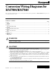
ON - OFF BURNER CONTROL 1.) RECYCLE MODULATING BURNER CONTROL RM7800M1011 WITH DISPLAY RM7800M1003 WITH DISPLAY RM7840M1017 WITHOUT DISPLAY RM7840M1009 WITHOUT DISPLAY SELECT A RELAY MODULE 60 HZ 50 HZ 60 HZ 50 HZ SELECT A SUBBASE 3.) SELECT A PURGE CARD 5.) OR RM7800G1018 WITH DISPLAY RM7800G1000 WITH DISPLAY RM7840G1014 WITHOUT DISPLAY RM7840G1006 WITHOUT DISPLAY 60 HZ 50 HZ 60 HZ 50 HZ 1 Q7800A1005 PANEL MOUNT OR Q7800B1003 BURNER/WALL MOUNT 2.) 4.
LOCKOUT MODULATION BURNER CONTROL 1.) SELECT A RELAY MODULE 2.) SELECT A SUBBASE 3.) SELECT A PURGE CARD 4.) 5.) SELECT A FLAME AMPLIFIER SELECT OPTIONS RM7800E1010 OR RM7800L1012 WITH DISPLAY 60 HZ RM7800E1002 OR RM7800L1004 WITH DISPLAY 50 HZ RM7840E1016 OR RM7840L1018 WITHOUT DISPLAY 60 HZ RM7840E1008 OR RM7840L1000 WITHOUT DISPLAY 50 HZ 1 2 Q7800A1005 PANEL MOUNT OR Q7800B1003 BURNER/WALL MOUNT ST7800A1005 2 SEC. ST7800A1013 7 SEC. ST7800A1021 10 SEC. ST7800A1039 30 SEC. ST7800A1047 40 SEC.
DIRECTIONS: 1. Disconnect all power to control being replaced. Note that more than one power supply disconnect may be involved. 2. Remove old control from subbase. 3. Mark all wires on subbase; i.e., wires connected to terminal 1 should be marked 1. 4. Disconnect wires from subbase. 5. Remove old subbase. 6. Mount Q7800 Subbase. 7. Connect wires to subbase according to wiring conversion for control being replaced. Pay close attention to footnotes.
Section I BC7000 65-0100—2 6
800 SERIES CONVERSION WIRING DIAGRAM BC700L1000 WITH PM720G2005 OR G2103 FROM________________________________ (DEVICE TO BE MODERNIZED) RM7800G1018 TO ______________________ (O.S.
7800 SERIES CONVERSION WIRING DIAGRAM BC7000L1000 WITH PM720L1030, 1139, L2020 FROM________________________________ (DEVICE TO BE MODERNIZED) RM7800L1012 OR RM7800E1010 TO ______________________ (O.S.
7800 SERIES CONVERSION WIRING DIAGRAM BC7000L1000 WITH PM720L2004 FROM________________________________ (DEVICE TO BE MODERNIZED) RM7800E1010 TO ______________________ (O.S.
7800 SERIES CONVERSION WIRING DIAGRAM BC700L1000 WITH PM720M2002 FROM________________________________ (DEVICE TO BE MODERNIZED) RM7800M1011 TO ______________________ (O.S.
7800 SERIES CONVERSION WIRING DIAGRAM BC7000L1000 WITH PM720M2036 FROM________________________________ (DEVICE TO BE MODERNIZED) RM7800M1011 TO ______________________ (O.S.
Section II Honeywell R4140, R4150 65-0100—2 12
7800 SERIES CONVERSION WIRING DIAGRAM R4140G WITH OR RM7800G1018 START INTERLOCKS FROM________________________________ TO RM7840G1014 ______________________ (DEVICE TO BE MODERNIZED) (O.S.
7800 SERIES CONVERSION WIRING DIAGRAM R4140G WITH PREIGNITION INTERLOCK FROM________________________________ (DEVICE TO BE MODERNIZED) RM7840G1014 OR RM7800G1018 TO ______________________ (O.S.
7800 SERIES CONVERSION WIRING DIAGRAM R4140L/R4150L FROM________________________________ (DEVICE TO BE MODERNIZED) RM7840E1016 OR RM7800E1010 RM7840L1018 OR RM7800L1012 TO ______________________ (O.S.
7800 SERIES CONVERSION WIRING DIAGRAM R4140M/R4150M WITH OR RM7800M1011 START INTERLOCKS FROM________________________________ TO RM7840M1017 ______________________ (DEVICE TO BE MODERNIZED) (O.S.
7800 SERIES CONVERSION WIRING DIAGRAM R4140M/R4150M WITH PREIGNITION INTERLOCK FROM________________________________ (DEVICE TO BE MODERNIZED) RM7840M1017 OR RM7800M1011 TO ______________________ (O.S.
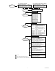
7800 SERIES CONVERSION WIRING DIAGRAM R4150A1007, A1023, A1122, A1247, OR RM7800M1011 A1254, A1288, B1005, C1003, C1029 FROM________________________________ TO RM7840M1017 ______________________ (DEVICE TO BE MODERNIZED) (O.S. NUMBER OF RELAY MODULE TO BE USED) FOR DIRECT SPARK IGNITION (OIL OR GAS) Q7800 G G 12 10 IGNITION TRANSFORMER 21 1ST STAGE FUEL VALVE D L2 13 L2 D 9 3 14 2ND STAGE FUEL VALVE (OPTIONAL) 9 L1&4 4 15 8 5 16 1 2 3 4 5 7 8 15 GENERAL FOOTNOTES, SEE PAGE 5.
7800 SERIES CONVERSION WIRING DIAGRAM R4150A1056, A1163, A1189, A1239 OR RM7800M1011 FROM________________________________ TO RM7840M1017 ______________________ (DEVICE TO BE MODERNIZED) (O.S.
7800 SERIES CONVERSION WIRING DIAGRAM R4150A1064, A1130, A1148 OR RM7800G1018 FROM________________________________ TO RM7840G1014 ______________________ (DEVICE TO BE MODERNIZED) (O.S. NUMBER OF RELAY MODULE TO BE USED) FOR DIRECT SPARK IGNITION (OIL OR GAS) Q7800 G G 12 10 IGNITION TRANSFORMER 21 1ST STAGE FUEL VALVE D L2 13 L2 D 9 3 14 2ND STAGE FUEL VALVE (OPTIONAL) 9 L1&4 4 15 8 5 16 1 2 3 4 5 7 8 15 GENERAL FOOTNOTES, SEE PAGE 5.
7800 SERIES CONVERSION WIRING DIAGRAM R4150A1080, A1155 RM7840G1014 OR RM7800G1018 FROM________________________________ TO ______________________ (DEVICE TO BE MODERNIZED) (O.S.
7800 SERIES CONVERSION WIRING DIAGRAM R4150A1106, A1171 OR RM7800M1011 FROM________________________________ TO RM7840M1017 ______________________ (DEVICE TO BE MODERNIZED) (O.S. NUMBER OF RELAY MODULE TO BE USED) FOR DIRECT SPARK IGNITION (OIL OR GAS) Q7800 G G 12 10 IGNITION TRANSFORMER 21 1ST STAGE FUEL VALVE D L2 13 L2 D 9 3 14 2ND STAGE FUEL VALVE (OPTIONAL) 9 L1&4 B 4 15 8 5 16 1 2 3 4 5 7 8 15 GENERAL FOOTNOTES, SEE PAGE 5.
7800 SERIES CONVERSION WIRING DIAGRAM R4150A1197 OR RM7800M1003 FROM________________________________ TO RM7840M1009, ______________________ (DEVICE TO BE MODERNIZED) (O.S. NUMBER OF RELAY MODULE TO BE USED) FOR DIRECT SPARK IGNITION (OIL OR GAS) Q7800 G G 12 10 IGNITION TRANSFORMER 21 1ST STAGE FUEL VALVE D L2 9 13 L2 D 3 14 2ND STAGE FUEL VALVE (OPTIONAL) 9 L1&4 8 4 15 5 16 1 2 3 4 5 7 8 15 GENERAL FOOTNOTES, SEE PAGE 5.
7800 SERIES CONVERSION WIRING DIAGRAM R4150G1004, 1046, 1111, 1145, 1178 OR RM7800G1018 FROM________________________________ TO RM7840G1014, ______________________ (DEVICE TO BE MODERNIZED) (O.S. NUMBER OF RELAY MODULE TO BE USED) FOR DIRECT SPARK IGNITION (OIL OR GAS) Q7800 G G L2 9 12 13 L2 3 14 10 10 IGNITION TRANSFORMER 21 1ST STAGE FUEL VALVE 11 14 C 2ND STAGE FUEL VALVE (OPTIONAL) 9 L1&4 8 4 15 5 16 12 1 2 3 4 5 7 8 15 GENERAL FOOTNOTES, SEE PAGE 5.
7800 SERIES CONVERSION WIRING DIAGRAM R4150G1012, G1079 OR RM7800M1011 FROM________________________________ TO RM7840M1017, ______________________ (DEVICE TO BE MODERNIZED) (O.S. NUMBER OF RELAY MODULE TO BE USED) FOR DIRECT SPARK IGNITION (OIL OR GAS) Q7800 G G L2 9 L1&4 8 12 13 L2 3 IGNITION TRANSFORMER 21 1ST STAGE FUEL VALVE 9 2ND STAGE FUEL VALVE (OPTIONAL) C 14 4 15 5 16 L2 10 1 2 3 4 5 7 8 15 GENERAL FOOTNOTES, SEE PAGE 5.
7800 SERIES CONVERSION WIRING DIAGRAM R4150G1103, G1137 OR RM7800G1018 FROM________________________________ TO RM7840G1014, ______________________ (DEVICE TO BE MODERNIZED) (O.S. NUMBER OF RELAY MODULE TO BE USED) FOR DIRECT SPARK IGNITION (OIL OR GAS) Q7800 G G L2 9 12 13 L2 3 14 10 10 IGNITION TRANSFORMER 21 1ST STAGE FUEL VALVE 11 14 D 2ND STAGE FUEL VALVE (OPTIONAL) 9 L1&4 8 4 15 5 16 12 1 2 3 4 5 7 8 15 GENERAL FOOTNOTES, SEE PAGE 5.
7800 SERIES CONVERSION WIRING DIAGRAM R4150G1129(GP200) R4140G1189(GP201) RM7840E1016 OR RM7800E1010 R4150L1078(GP300) R4140L1089(GP301) OR RM7800L1012 FROM________________________________ TO RM7840L1018 ______________________ (DEVICE TO BE MODERNIZED) (O.S.
7800 SERIES CONVERSION WIRING DIAGRAM RM7840G1014 OR RM7800G1018 R4150G1186 FROM________________________________ TO ______________________ (DEVICE TO BE MODERNIZED) (O.S.
7800 SERIES CONVERSION WIRING DIAGRAM R4150H1002 OR RM7800G1018 FROM________________________________ TO RM7840G1014, ______________________ (DEVICE TO BE MODERNIZED) (O.S. NUMBER OF RELAY MODULE TO BE USED) FOR DIRECT SPARK IGNITION (OIL OR GAS) Q7800 G G L2 9 12 13 L2 3 14 10 IGNITION TRANSFORMER 21 1ST STAGE FUEL VALVE 10 12 2ND STAGE FUEL VALVE (OPTIONAL) 9 L1&4 4 15 L2 11 D 8 5 16 1 2 3 4 7 8 15 GENERAL FOOTNOTES, SEE PAGE 5.
7800 SERIES CONVERSION WIRING DIAGRAM R4150M1175(GP100) R4140M1079(GP101) FROM________________________________ (DEVICE TO BE MODERNIZED) RM7840M1017 OR RM7800M1011 TO ______________________ (O.S. NUMBER OF RELAY MODULE TO BE USED) Q7800 G S2 B 15 5 16 6 17 7 18 5 8 19 7 9 20 18 10 21 6 S1 F 22 17 A 1 2 3 4 5 7 8 A 21 1ST STAGE FUEL VALVE 9 2ND STAGE FUEL VALVE (OPTIONAL) L2 LOCATE PREIGNITION INTERLOCK CONNECTION ON Q520 SUBBASE TERMINALS 13 AND 3.
Section III Honeywell R4126, R4127, R4181 31 65-0100—2
7800 SERIES CONVERSION WIRING DIAGRAM R4126A1008, 1016, A1024, A1032, A1040, A1057,A1081, A1149 R4126B1066,B1014,B1022 FROM________________________________ (DEVICE TO BE MODERNIZED) OR RM7800G1018 TO RM7840G1014, ______________________ (O.S.
7800 SERIES CONVERSION WIRING DIAGRAM For Insurance Requirements R4126A1008, A1016, A1024, A1032 A1040, A1057, A1081, A1149 R4126B1006, B1014, B1022 FROM________________________________ (DEVICE TO BE MODERNIZED) TO RM7840E1016, RM7800E1010 RM7840L1018, RM7800L1012 ______________________ (O.S.
7800 SERIES CONVERSION WIRING DIAGRAM R4126A1073, A1164 FROM________________________________ (DEVICE TO BE MODERNIZED) TO RM7840E1016 OR RM7800E1010 RM7840L1018 0R RM7800L1012 ______________________ (O.S.
7800 SERIES CONVERSION WIRING DIAGRAM RM7840E1016 OR RM7800E1010 R4126A1172, A1180, A1198 OR RM7800L1012 FROM________________________________ TO RM7840L1018 ______________________ (DEVICE TO BE MODERNIZED) (O.S. NUMBER OF RELAY MODULE TO BE USED) Q7800 G G 12 FOR DIRECT SPARK IGNITION (OIL OR GAS) 11 10 L2 L2 13 IGNITION TRANSFORMER C 8 9 3 14 13 9 3&4 L1 4 15 8 5 16 F 6 17 F2 7 18 5 7 14 B 1 8 19 L2 MAIN VALVE 12 C A.
7800 SERIES CONVERSION WIRING DIAGRAM R4127A1007, A1015,1023, A1031, A1049 A1064, A1089, A1130, A1189, B1005, B1013, B1021, B1047, C1003 FROM________________________________ (DEVICE TO BE MODERNIZED) RM7840G1014 OR RM7800G1018 TO ______________________ (O.S.
7800 SERIES CONVERSION WIRING DIAGRAM R4127A1056, A1080, A1122, A1148 A1155, A1171, A1197, B1039, B1054 FROM________________________________ (DEVICE TO BE MODERNIZED) RM7840G1014 OR RM7800G1018 TO ______________________ (O.S.
7800 SERIES CONVERSION WIRING DIAGRAM R4127A1171, B1039, B1047, B1054 (RAY BURNER) RM7800G1018 OR RM7840G1014 FROM________________________________ TO ______________________ (DEVICE TO BE MODERNIZED) (O.S.
7800 SERIES CONVERSION WIRING DIAGRAM For Insurance Requirements R4127 (ALL MODELS) FROM________________________________ (DEVICE TO BE MODERNIZED) TO RM7840E1016 OR RM7800E1010 RM7840L1018 OR RM7800L1012 ______________________ (O.S.
7800 SERIES CONVERSION WIRING DIAGRAM R4181A1000, A1026 RM7840G1014 OR RM7800G1018 FROM________________________________ TO ______________________ (DEVICE TO BE MODERNIZED) (O.S. NUMBER OF RELAY MODULE TO BE USED) Q7800 G G 2 (L2) + 15 12 13 L2 3 9 14 8 5 16 A 6 17 4 7 18 18 E 8 19 C 9 20 B F D 10 21 F 22 A B START INTERLOCKS 4 AIRFLOW SWITCH LOCATE THE START INTERLOCKS AT THIS POINT AND CONNECT IT TO Q7800 SUBBASE TERMINAL 20.
7800 SERIES CONVERSION WIRING DIAGRAM For Insurance Requirements R4181A1000, A1026 FROM________________________________ (DEVICE TO BE MODERNIZED) TO RM7840E1016 OR RM7800E1010 RM7840L1018 OR RM7800L1012 ______________________ (O.S. NUMBER OF RELAY MODULE TO BE USED) FOR DIRECT SPARK IGNITION (OIL OR GAS) Q7800 G G 12 13 IGNITION TRANSFORMER 10 2 (L2) + 15 13 L2 12 8 9 3 14 L2 10 MAIN VALVE 9 1 (L1) + 3 8 4 15 5 16 11 1 2 3 4 5 7 8 15 16 18 GENERAL FOOTNOTES, SEE PAGE 5.
7800 SERIES CONVERSION WIRING DIAGRAM RM7840E1016 OR RM7800E1010 R4181A1018, A1034 RM7840L1018 OR RM7800L1012 FROM________________________________ TO ______________________ (DEVICE TO BE MODERNIZED) (O.S.
7800 SERIES CONVERSION WIRING DIAGRAM R4181A1042, A1059 FROM________________________________ (DEVICE TO BE MODERNIZED) TO RM7840E1016 OR RM7800E1010 RM7840L1018 OR RM7800L1012 ______________________ (O.S. NUMBER OF RELAY MODULE TO BE USED) Q7800 G G 12 FOR DIRECT SPARK IGNITION (OIL OR GAS) 13 IGNITION TRANSFORMER 10 2, L2 L2 13 C 8 9 3 14 L2 10 MAIN VALVE 9 1, L1 8 3,4 B 4 15 5 16 6 11 1 2 3 4 5 7 8 15 16 18 GENERAL FOOTNOTES, SEE PAGE 5.
Section IV Fireye C, D, and E Series 65-0100—2 44
7800 SERIES CONVERSION WIRING DIAGRAM FIREYE 70D10, 26CF6 5022, 26CU6 5065 RM7840E1016 OR RM7800E1010 EP160/EP161/EP170 RM7840L1018 OR RM7800L1012 FROM________________________________ TO ______________________ (DEVICE TO BE MODERNIZED) (O.S.
7800 SERIES CONVERSION WIRING DIAGRAM For Replacement FIREYE 24CJ5 5010/5011/3010/3011 25CU6 5062/5063/RS2E 26CF6 5020/5021/1010/1011 70D30 EP380/EP381/EP390 FROM________________________________ (DEVICE TO BE MODERNIZED) RM7840M1017 OR RM7800M1011 TO ______________________ (O.S.
7800 SERIES CONVERSION WIRING DIAGRAM For Insurance Requirements FIREYE 24CJ5 5010/5011/3010/3011 25CU6 5062/5063/RS2E 26CF6 5020/5021/1010/1011 70D30 EP380/EP381/EP390 FROM________________________________ (DEVICE TO BE MODERNIZED) RM7840E1016 OR RM7800E1010 OR RM7800L1012 TO RM7840L1018 ______________________ (O.S.
7800 SERIES CONVERSION WIRING DIAGRAM For Replacement FIREYE 24CJ5 5015 25CU6 5066 26CF6 5023 70D20 EP260&EP261/EP270 FROM________________________________ (DEVICE TO BE MODERNIZED) RM7840G1014 OR RM7800G1018 TO ______________________ (O.S.
7800 SERIES CONVERSION WIRING DIAGRAM For Insurance Requirements FIREYE 24CJ5 5015 25CU5 5066 26CF6 5023 70D20 EP260/EP261/EP270 FROM________________________________ (DEVICE TO BE MODERNIZED) RM7840E1016 OR RM7800E1010 RM7840L1018 OR RM7800L1012 TO ______________________ (O.S.
Section V Fireye P Series 65-0100—2 50
7800 SERIES CONVERSION WIRING DIAGRAM 25CU6 - 1050 RM7840M1017 FROM________________________________ TO ______________________ (DEVICE TO BE MODERNIZED) (O.S.
7800 SERIES CONVERSION WIRING DIAGRAM For Replacement FIREYE 26RJ8 1016, 1016T 26RJ8 1012, 1012T, 6012, 6016 FROM________________________________ (DEVICE TO BE MODERNIZED) RM7840G1014 OR RM7800G1018 TO ______________________ (O.S.
7800 SERIES CONVERSION WIRING DIAGRAM FIREYE 26RJ8 1016, 1016T RM7840E1016 OR RM7800E1010 26RJ8 1012, 1012T, 6012, 6016 OR RM7800L1012 FROM________________________________ TO RM7840L1018 ______________________ (DEVICE TO BE MODERNIZED) (O.S.
7800 SERIES CONVERSION WIRING DIAGRAM RM7840E1016 OR RM7800E1010 FIREYE 25RU8 4580 OR RM7800L1012 FROM________________________________ TO RM7840L1018 ______________________ (DEVICE TO BE MODERNIZED) (O.S.
7800 SERIES CONVERSION WIRING DIAGRAM FIREYE 25RU8 6560, 6570, 6580 26RJ8 6060, 6070, 6080(D), 6160 FROM________________________________ (DEVICE TO BE MODERNIZED) RM7840E1016 OR RM7800E1010 OR RM7800L1012 TO RM7840L1018 ______________________ (O.S.
7800 SERIES CONVERSION WIRING DIAGRAM FIREYE 29RF5 1001, 1009, 6009 FROM_______________________ (DEVICE TO BE MODERNIZED) RM7840G1014 OR RM7800G1018 TO _______________________ (O.S.
7800 SERIES CONVERSION WIRING DIAGRAM FIREYE 26RJ8 6058, 6066, 6068 OR RM7800G1018 25RU8 6558, 6566 FROM________________________________ TO RM7840G1014 ______________________ (DEVICE TO BE MODERNIZED) (O.S.
7800 SERIES CONVERSION WIRING DIAGRAM FIREYE 26RJ8 1002, 1003, 1008, 1011, 1018, 6008, 6018 29RF5 1000, 1002, 1005, 1015, 1104 29RF5 6015 FROM________________________________ (DEVICE TO BE MODERNIZED) OR RM7800G1018 TO RM7840G1014 ______________________ (O.S.
Section VI Eclipse 59 65-0100—2
7800 SERIES CONVERSION WIRING DIAGRAM Lockout Modulation ECLIPSE 5602 RM7800L1012 OR RM7840L1018 FROM________________________________ TO ______________________ (DEVICE TO BE MODERNIZED) (O.S.