
Install Instructions


5 65-0100—2
DIRECTIONS:
1. Disconnect all power to control being replaced. Note
that more than one power supply disconnect may be
involved.
2. Remove old control from subbase.
3. Mark all wires on subbase; i.e., wires connected to
terminal 1 should be marked 1.
4. Disconnect wires from subbase.
5. Remove old subbase.
6. Mount Q7800 Subbase.
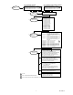
7. Connect wires to subbase according to wiring conver-
sion for control being replaced. Pay close attention to
footnotes. The triangle symbol with a number or
letter inside designates a footnote.
8. Install the RM7800/RM7840 control. Make sure the
proper ST7800 purge card and flame detector were
selected for the application.
9. The RM7800/RM7840 have two or three site con-
figurable jumper options. (depends on model number).
JUMPERS:
• JR1 selects Pilot Flame Establishing Period.
• JR2 (RM7800G/RM7840G only) selects intermit-
tent or interrupted pilot.
• JR3 selects lockout/running interlock input
check. Refer to RM7800 instructions, 60-0117 or
RM7840 instructions, 60-0087, for assistance and
proper selection.
10. Refer to instructions, 60-0087 or 60-0117, for check-
out and start-up.
GENERAL FOOTNOTES:
1
RM7840 operates the same as the RM7800 but does
not have the Display Module. (Display Module
S7800A1001 can be added later.) The RM7800 must
have Display Module installed to operate.
2
Select proper prepurge timer according to the Firing
Line cross reference, 70-8313.
3
Select proper flame amplifier according to the Firing
Line amplifier cross reference.
4
Proper grounding of the green subbase terminal screw
to an electrical earth ground is a MUST for proper
operation of the 7800 SERIES device.
5
NOTE: UL allows only two electrical wires to each
subbase terminal. Wiring information may show more
than two wires to a particular terminal, which may
require an external connection to accomplish the
connection.
6
Q520 Subbase terminal 16 connection may have been
a wire nut connection. Remove wire nut and connect
to the Q7800 Subbase terminal 6.
1
7
Select proper site configurable jumpers specified in
the cross reference and shown in the Specifications,
65-0087 for RM7840 or 65-0117 for RM7800.
8
Select proper site configurable PFEP/MFEP speci-
fied in the cross reference and shown in the Specifica-
tions, 65-0087 for RM7840 or 65-0117 for RM7800.
9
If low fire switch is not used, a jumper is required
between Q7800 Subbase terminals 5 and 18. NOTE:
This jumper will add 30 seconds to prepurge timing.
10
If replaced device had interrupted pilot on terminal 6,
connect to Q7800 Subbase terminal 8.
11
Locate the start interlock on the Q520 Subbase termi-
nal 16 and connect between Q7800 terminals 4 and
20. The start interlocks now become preignition
interlocks. If start interlocks are not used, jumper the
Q7800 Subbase terminal 4 to terminal 20.
12
Locate the preignition interlocks on the Q520 Sub-
base terminals 4 and 16. Connect the preignition
interlock between the Q7800 Subbase terminals 4
and 20. If preignition interlocks are not used, jumper
the Q7800 Subbase terminal 4 to terminal 20.
13
Jumper Q7800 subbase terminal 8 to terminal 19 for
30 second MFEP.
14
Locate the preignition interlock connection on the
Q520 Subbase terminal 16 and connect to the Q7800
subbase terminal 20.
15
For direct spark ignition, discard any jumpers be-
tween Q520 Subbase terminals 5, 6, and 7 and con-
nect according to the diagram shown.
16
Many R4181 devices were used on North American
Company Burners. Because North American uses
many unique external circuits, such as Automatic
Fuel Changeover, Valve Leak Checker, etc., it is
recommended that you contact Honeywell through
your local distributor or sales representative before
attempting conversions of North American Burners.
17
For models without damper motors, jumper Q7800
Subbase terminal 14 to terminal 18, and terminal 4 to
terminal 13.
18
Be sure system is modernized to 120 Vac. The
replacement 7800 SERIES control is 120 volts.
19 Select proper flame detector when converting from a
non-Honeywell control or when a different flame
detection system is desired; i.e., the old flame ampli-
fier was flame rectification and the new flame ampli-
fier is to be ultraviolet. Refer to product selection
matrixes on pages 3 and 4.