
Product Overview


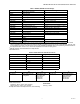
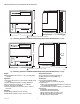
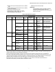
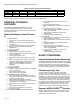
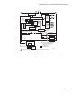
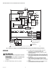
Table Of Contents
- Application
- Features
- Optional Features
- Specifications
- Principal Technical Features
- Safety Provisions
- Internal Hardware Status Monitoring
- Closed Loop Logic Test
- Dynamic AMPLI-CHECKTM Circuitry
- Dynamic Input Check
- Dynamic Safety Relay Test
- Dynamic Self-Check Safety Circuit
- Expanded Safe-Start Check
- Off Cycle (Standby) Flame Signal Check
- Tamper Resistant Timing and Logic
- Verified Spark Termination
- First-Out Annunciation and Self- Diagnostics
- Interlock Requirements (RM7895 Only)
- Installation
- Wiring
- Assembly
- Operation
- Initiate
- Standby
- Static Checkout
- Checkout
- Equipment Recommended
- Checkout Summary
- Preliminary Inspection
- Flame Signal Measurement
- Initial Lightoff Check for Proved Pilot
- Initial Lightoff Check for Direct Spark Ignition (DSI)
- Pilot Turndown Test (All Installations Using a Pilot)
- Ignition Interference Test (All Flame Rods)
- To Eliminate Ignition Interference
- Flame Signal with Hot Combustion Chamber (All Installations)
- Safety Shutdown Tests (All Installations)
- Troubleshooting
RM7890; RM7895 100 VAC 7800 SERIES RELAY MODULES
66-1195—01 8
IMPORTANT
1. Wiring connections for the relay modules are unique;
refer to Fig. 6 and 7 or the correct Specifications for
proper subbase wiring.
2. Wiring must comply with all applicable codes,
ordinances and regulations.
3. Wiring must comply with NEC Class 1 (Line Voltage)
wiring.
4. Loads connected to the relay module must not
exceed those listed on the relay module label or the
Specifications; see Table 1.
5. Limits and interlocks must be rated to simultaneously
carry and break current to the ignition transformer,
pilot valve, and main fuel valve(s).
6. All external timers must be Listed or Component-
Recognized by authorities who have proper
jurisdiction.
7. For on-off gas-fired systems, some authorities who
have jurisdiction prohibit the wiring of any limit or
operating contacts in series between the flame
safeguard control and the main fuel valve(s).
8. Two flame detectors can be connected in parallel
with the exception of Flame Detectors C7915,
C7927,C7961 and C7962.
9. This equipment generates, uses and can radiate
radio frequency energy and, if not installed and used
in accordance with the instructions, can cause
interference with radio communications. It has been
tested and found to comply with the limits for a Class
B computing device of Part 15 of FCC rules which
are designed to provide reasonable protection
against such interference when operated in a
commercial environment. Operation of this
equipment in a residential area may cause
interference; in which case, the users at their own
expense may be required to take whatever measures
are required to correct this interference.
10.This digital apparatus does not exceed the Class B
limits for radio noise for digital apparatus set out in
the Radio Interference Regulations of the Canadian
Department of Communications.
Location
Humidity
Install the relay module where the relative humidity never
reaches the saturation point. The relay module is designed to
operate in a maximum 85% relative humidity continuous,
noncondensing, moisture environment. Condensing moisture
can cause a safety shutdown.
Vibration
Do not install the relay module where it could be subjected to
vibration in excess of 0.5G continuous maximum vibration.
Weather
The relay module is not designed to be weather tight. When
installed outdoors, locate the relay module inside an approved
weather-tight enclosure.
Mounting Wiring Subbase
See Fig. 1 and 2 for installation dimensions.
1. Mount the subbase in any position except horizontally
with the bifurcated contacts pointing down. The
standard vertical position is recommended. Any other
position decreases the maximum ambient temperature
rating.
2. Select a location on a wall, burner or electrical panel.
The Q7800 can be mounted directly in the control
cabinet. Be sure to allow adequate clearance for
servicing, installation, access or removal of the relay
module, expanded annunciator, KDM, flame amplifier,
flame amplifier signal voltage probes, run/test switch,
electrical signal voltage probes and electrical field
connections.
3. For surface mounting, use the back of the subbase as a
template to mark the four screw locations. Drill the pilot
holes.
4. Securely mount the subbase using four no. 6 screws
(not provided).