
Install Instructions
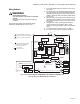
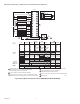
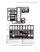
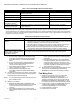
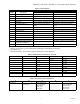
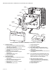
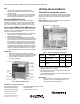
Table Of Contents

RM7895A,B,C,D/EC7895A,C; RM7896A,B,C,D 7800 SERIES RELAY MODULES
Automation and Control Solutions
Honeywell International Inc. Honeywell Limited-Honeywell Limitée
1985 Douglas Drive North 35 Dynamic Drive
Golden Valley, MN 55422 Toronto, Ontario M1V 4Z9
customer.honeywell.com
® U.S. Registered Trademark
© 2007 Honeywell International Inc.
66-1090—06 M.S. Rev. 06-07
Run
1. The EC7895C, RM7895C,D, RM7896C,D has a
delayed main valve that is energized once the RUN
period is entered.
2. The relay module is now in RUN and remains in RUN
until the controller input, terminal 6, opens, indicating
that the demand is satisfied or a limit has opened.
Post Purge (RM7896A,B,C,D Only)
After demand is satisfied or a limit opens, de-energizing
terminal 6, the Ignition/Pilot valve, main valve and delayed
main valve, terminals 8, 9 and 21, are de-energized. The
blower motor, terminal 4, remains powered for 15 seconds.
Run/Test Switch (RM/EC7895C,D; RM7896C,D only)
The Run/Test Switch is located on the top side of the relay
module, see Fig. 5. The Run/Test Switch allows the burner
sequence to be altered as follows:
1. In the measured PREPURGE sequence, the Run/Test
Switch, placed in the TEST position, causes the
PREPURGE timing to stop.
2. In the Pilot Flame Establishing Period, the Run/Test
Switch, placed in the TEST position, stops the timer dur-
ing the first eight seconds of a ten-second PFEP selec-
tion or during the first three seconds of a four-second
PFEP selection. It also allows for pilot turn-down test
and other burner adjustments. This activates a fifteen-
second flameout timer that permits pilot flame adjust-
ment without nuisance safety shutdowns. The Run/Test
Switch is ignored during PFEP for the C and D relay
modules if terminals 8 and 9 or 9 and 21 are jumpered.
IMPORTANT
When the relay module is switched to the TEST
mode, it stops and holds at the next Run/Test Switch
point in the operating sequence. Make sure that the
Run/Test Switch is in the RUN position before
leaving the installation.
Fig. 5. Sequence Status LEDs.
SETTINGS AND ADJUSTMENTS
Selectable Site-Configurable Jumpers
The relay module has three site-configurable jumper options,
see Fig. 6 and Table 6. If necessary, clip the site-configurable
jumpers with side cutters and remove the resistors from the
relay module.
SERVICE NOTE: Clipping and removing a site-configurable
jumper enhances the level of safety.
Fig. 6. Selectable site-configurable jumpers.
Table 7. Site-configurable jumper options.
a
The RM7895C1020 and RM7896C1036 have fixed PFEP
of ten seconds and do not have jumper JR1 (3 seconds
software revision 4151 or greater).
b
The RM7895C1053 has fixed PFEP of four seconds and
does not have jumper JR1.
c
The RM7895C1053 locks out on Flame Failure Action and
does not have jumper JR2.
IMPORTANT
Clipping and removing a jumper after 200 hours of
operation causes a nonresettable Fault 110. The
relay module must then be replaced.
SEQUENCE
STATUS
LEDs
RESET
PUSHBUTTON
FLAME
SIMULATOR INPUT
FLAME CURRENT
TEST JACKS
RUN/TEST SWITCH
CAPTIVE
MOUNTING
SCREW
PLUG-IN
PURGE
CARD
DUST
COVER
RELAY
MODULE
FLAME
AMPLIFIER
M7552A
Jumper
Number Description Intact Clipped
JR1
a, b
Pilot Flame Establishing
Period (PFEP)
10
seconds
4 seconds
JR2
c
Flame Failure Action Recycle Lockout
JR3 Airflow Switch (ILK)
Failure
Recycle Lockout
RUN/TEST SWITCH
(EC7895C; RM7895C,D; RM7896C,D)
SELECTABLE CONFIGURATION JUMPERS
M7553A