
Install Instructions
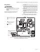
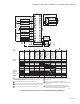
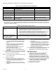
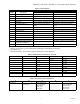
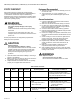
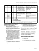
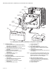
Table Of Contents

RM7895A,B,C,D/EC7895A,C; RM7896A,B,C,D 7800 SERIES RELAY MODULES
9 66-1090—06
Mounting RM7895A,B,C,D/EC7895A,C;
RM7896A,B,C,D Relay Module
1. Mount the RM7895A,B,C,D/EC7895A,C;
RM7896A,B,C,D vertically on the Q7800 Subbase or
mount horizontally with the knife blade terminals
pointing down. When mounted on the Q7800A, the
RM7895A,B,C,D/EC7895A,C; RM7896A,B,C,D must be
in an electrical enclosure.
2. When mounting in an electrical enclosure, provide ade-
quate clearance for servicing, installation and removal
of the RM7895A,B,C,D/EC7895A,C; RM7896A,B,C,D,
KDM, flame amplifier, flame amplifier signal voltage
probes, electrical signal voltage probes and electrical
connections.
a. Allow an additional two inches (51 mm) below the
RM7895A,B,C,D/EC7895A,C; RM7896A,B,C,D for
the flame amplifier mounting.
b. Allow an optional three-inch (76 mm) minimum on
both sides of the RM7895A,B,C,D/EC7895A,C;
RM7896A,B,C,D for electrical signal voltage probes.
3. Make sure no subbase wiring is projecting beyond the
terminal blocks. Tuck in wiring against the back of the
subbase so it does not interfere with the knife blade ter-
minals or bifurcated contacts.
IMPORTANT
The RM7895A,B,C,D/EC7895A,C; RM7896A,B,C,D
must be installed with a plug-in motion rather than a
hinge action.
4. Mount the RM7895A,B,C,D/EC7895A,C;
RM7896A,B,C,D by aligning the four L-shaped corner
guides and knife blade terminals with the bifurcated
contacts on the wiring subbase and securely tightening
the two screws without deforming the plastic.
Mounting Other System Components (Fig. 4)
Refer to the applicable specifications for mounting other
system components.
PRINCIPAL TECHNICAL FEATURES
The RM7895 provides all customary flame safeguard
functions as well as significant advancements in safety,
annunciation, and system diagnostics.
Safety Shutdown (Lockout) Occurs if:
1. INITIATE PERIOD
a. Purge card is not installed or removed.
b. Purge card is bad.
c. Configuration jumpers have been changed (after
200 hours)—Fault Code 110.
d. AC line power errors occurred, see Operation.
e. Four minute INITIATE period has been exceeded.
5 All 5-8 — 1. Ignition spark (if ignition
transformer is connected to
terminal 8).
2. Automatic pilot valve opens
(if connected to terminal 8).
NOTE: Refer to wiring diagram
of system being tested.
1. Watch for spark or listen for buzz.
2. Listen for click or feel head of valve for
activation.
a. Actuator if used.
b. Pilot valve.
6 All 5-9 — Automatic fuel valve(s) open(s). If
using direct spark ignition, check
first stage fuel valve(s) instead of
pilot valve.
Same as test 5. If using direct spark
ignition, check first stage fuel valve(s)
instead of pilot valve.
7 EC7895C;
RM7895C,D;
RM7896C,D
5-21 — Automatic second stage main fuel
valve(s) open(s).
1. Listen for and observe operation of
second stage main fuel valve(s) and
actuator(s).
2. Valve(s) and actuator(s).
8 All 5-3 — Alarm (if used) turns on. 1. Alarm.
Final All
CAUTION
Equipment Damage Hazard.
Can cause equipment damage.
After completing these tests, open master switch and remove all test jumpers from subbase
terminals. Also remove bypass jumpers, if used, from low fuel pressure limits.
Table 6. Static Checkout (Continued).
Test
Number
Relay Module
Model
Test
Jumpers Voltmeter Normal Operation
If Operation is Abnormal,
Check Items Listed Below