
Install Instructions
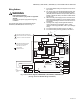
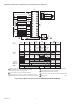
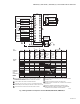
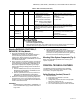
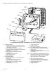
Table Of Contents

RM7895A,B,C,D/EC7895A,C; RM7896A,B,C,D 7800 SERIES RELAY MODULES
66-1090—06 10
Fig. 4. RM7895A,B,C,D/EC7895A,C; RM7896A,B,C,D Relay Module, exploded view.
2. STANDBY PERIOD
a. Airflow lockout feature is enabled and the airflow
switch does not close after ten seconds or within the
specified purge card timing.
b. Flame signal is detected after 30 seconds.
c. Ignition/pilot valve/intermittent pilot valve terminal is
energized.
d. Main valve terminal is energized.
e. Delayed main valve terminal is energized
(RM7895C,D).
f. Internal system fault occurred.
g. Purge card is removed.
h. Purge card is bad.
3. PREPURGE PERIOD
a. Airflow lockout feature is enabled and the airflow
switch opens.
b. Ignition/pilot valve terminal is energized.
c. Main valve terminal is energized.
d. Delayed main valve terminal is energized
(RM7895C,D).
e. Internal system fault occurred.
f. Purge card is removed.
g. Purge card is bad.
h. Flame signal is detected.
4. PILOT FLAME ESTABLISHING PERIOD (PFEP)
a. Airflow lockout feature is enabled and the airflow
switch opens.
b. No flame signal at end of PFEP.
c. Ignition/pilot valve/intermittent pilot valve terminal is
not energized.
NOTE: For the RM7895C1020 and RM7896C1036, during
the first 8 seconds of PFEP, when a flame signal is
detected, terminal 10 is de-energized. If the flame
signal is lost, terminal 10 will re-energize.
d. Main valve terminal is energized.
e. Delayed (second stage) main valve terminal is
energized (RM7895C,D/EC7895C; RM7896C,D).
f. Internal system fault occurred.
g. Purge card is removed.
h. Purge card is bad.
HONEYWELL
P
OWER
PI
LOT
F
LAM
E
MAIN
A
L
ARM
RES
E
T
DUST
COVER
PURGE
TIMER
WIRING
SUBBASE
CAPTIVE
MOUNTING
SCREW
RUN/TEST (C,D ONLY)
SWITCH
CONFIGURATION
JUMPERS
RELAY
MODULE
SEQUENCE
STATUS
LED PANEL
RESET
BUTTON
FLAME
AMPLIFIER
B
URNE
R
CONTROL
M15122