
Product Overview
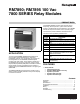
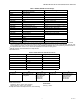
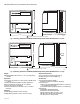
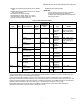
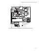
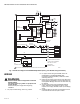
Table Of Contents
- Application
- Features
- Optional Features
- Specifications
- Principal Technical Features
- Safety Provisions
- Internal Hardware Status Monitoring
- Closed Loop Logic Test
- Dynamic AMPLI-CHECKTM Circuitry
- Dynamic Input Check
- Dynamic Safety Relay Test
- Dynamic Self-Check Safety Circuit
- Expanded Safe-Start Check
- Off Cycle (Standby) Flame Signal Check
- Tamper Resistant Timing and Logic
- Verified Spark Termination
- First-Out Annunciation and Self- Diagnostics
- Interlock Requirements (RM7895 Only)
- Installation
- Wiring
- Assembly
- Operation
- Initiate
- Standby
- Static Checkout
- Checkout
- Equipment Recommended
- Checkout Summary
- Preliminary Inspection
- Flame Signal Measurement
- Initial Lightoff Check for Proved Pilot
- Initial Lightoff Check for Direct Spark Ignition (DSI)
- Pilot Turndown Test (All Installations Using a Pilot)
- Ignition Interference Test (All Flame Rods)
- To Eliminate Ignition Interference
- Flame Signal with Hot Combustion Chamber (All Installations)
- Safety Shutdown Tests (All Installations)
- Troubleshooting

RM7890; RM7895 100 VAC 7800 SERIES RELAY MODULES
3 66-1195—01
Table 1. RM7890, RM7895 Terminal Ratings.
a
The RM7890 and RM7895 must have an earth ground providing a connection between the wiring subbase and the control
panel or equipment. The earth ground wire must be capable of conducting the current to blow a 15A Fast Blow, Type SC, fuse
(or equivalent) in the event of an internal short circuit. The RM7890 and RM7895 need a low impedance ground connection to
the equipment frame, which, in turn, needs a low impedance connection to earth ground.
b
2000 VA maximum connected load to the Relay Module.
c
See Table 2 and 3.
Table 2. Combinations for terminals 8, 9 and 10.
Table 3. Composition of Each Combination.
Environmental Ratings:
Ambient Temperature:
Operating: -40°F to 140°F (-40°C to 60°C).
Storage: -60°F to 150°F (-51°C to 66°C).
Humidity: 85% relative humidity continuous, noncondensing.
Vibration: 0.5G environment.
Dimensions:
See Fig. 1 and 2.
Terminal No. Description Ratings
G
Flame Sensor Ground
a
—
Earth G
Earth Ground
a
—
L2(N) Line Voltage Common —
3 (RM7890) Line Voltage Supply (L1)
100 Vac (+10%/-15%), 50/60 Hz (±10%).
b
3 (RM7895) Alarm 100 Vac, 1A pilot duty.
4 (RM7890) Alarm 100 Vac, 1A pilot duty.
4 (RM7895) Burner Motor 100 Vac, 9.8AFL, 58.8ALR (inrush).
5 (RM7890) Unused —
5 (RM7895) Line Voltage Supply (L1)
100 Vac (+10%/-15%), 50/60 Hz (±10%).
b
6 (RM7890) Burner Controller and Limits
100 Vac 8A Run, 43A inrush.
b
6 (RM7895) Burner Controller and Limits 100 Vac, 1 mA.
7 (RM7890) Unused —
7 (RM7895) Airflow Interlock 100 Vac, 8A run, 43A inrush.
8 Pilot Valve/Ignition
100 Vac.
c
9 Main Fuel Valve
10 Ignition
F(11) Flame Sensor 60–220 Vac, current limited.
12 to 22 Unused —
Pilot Valve (Terminal 8) Main Fuel Valve (Terminal 9) Ignition (Terminal 10)
CFA
B F No Load
FFA
F No Load A
DFA
DDA
D No Load A
ABCDF
4.5A ignition 50 VA Pilot Duty plus
4.5A ignition.
180 VA ignition plus
motor valves with:
660 VA inrush
360 VA open
250 VA hold.
2A Pilot Duty 65 VA Pilot Duty plus
Motor valves with:
3850 VA inrush
700 VA open
250 VA hold.