
Install Instructions
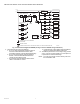
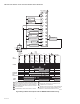
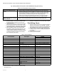
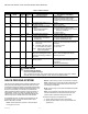
Table Of Contents

RM7898A 7800 SERIES VALVE PROVING PRIMARY RELAY MODULES
66-1161—04 4
Fig. 2. Internal block diagram of RM7898 (see Fig. 4 and 5 for detailed wiring instructions).
7. Recommended wire routing of leadwires:
a. Do not run high voltage ignition transformer wires in
the same conduit with the flame detector, Data
ControlBus™ Module, or Remote Reset Module wiring.
b. Do not route flame detector, Data ControlBus™
Module, or Remote Reset Module leadwires in
conduit with line voltage circuits.
c. Enclose flame detector leadwires without armor
cable in metal cable or conduit.
d. Follow directions in flame detector, Data ControlBus™
Module, or Remote Reset Module Instructions.
8. The KDM is powered from a low voltage, energy limited
source. It can be mounted outside of a control panel if it
is protected from mechanical damage.
NOTE: A 13 Vdc power supply must be used any time more
than one KDM is used.
L1
L2
BLOWER
ALARM
INTERNAL
ELECTRONICS
DEMAND
LIMITS
VALVE PROVING
SWITCH
PILOT SELECT
PREIGNITION
INTERLOCK
PLUG IN
FLAME
AMPLIFIER
INTERNAL RELAY OPTO FEEDBACK
FIELD WIRING
INTERNAL WIRING
3K
6K
1K
4K
2K
2K
5K
7K
AIRFLOW
SWITCH
M23870A
3
5
L2
4
PILOT
VALVE
8
9
MAIN
VALVE 1
10
IGNITION
MAIN
VALVE 2
21
22
DETECTOR
SHUTTER
F
G
6
CONTROLLER
OR
DEMAND
17
7
FLAME
DETECTOR
DSI SELECT FOR
VP MODE
20
18
19
16
1
ALTERNATE CONNECTION IF VALVE PROVING BOTH, SPLIT OR AFTER ARE SELECTED.
1