
Install Instructions
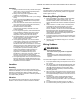
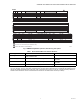
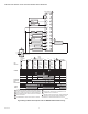
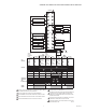
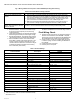
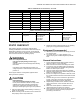
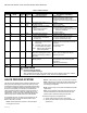
Table Of Contents

RM7898A 7800 SERIES VALVE PROVING PRIMARY RELAY MODULES
5 66-1161—04
Fig. 3. RM7898 Relay Module operation, Valve Proving Test options.
Table 1. Recommended Wire Sizes and Part Numbers.
a
The KDM, Data ControlBus™ Module (for remote mounting or communications) must be wired in daisy chain configuration,
1(a)-1(a), 2(b)-2(b), 3(c)-3(c). The order of interconnection of all the devices listed above is not important. Be aware that mod-
ules on the closest and farthest end of the daisy chain configuration string require a 120 ohm (1/4 watt minimum) resistor ter-
mination across terminals 1 and 2 of the electrical connectors for connections over 100 feet (31 meters).
Application Recommended Wire Size Recommended Part Numbers
Line voltage terminals. 14, 16 or 18 AWG copper conductor, 600 volt insulation,
moisture-resistant wire.
TTW60C, THW75C, THHN90C.
Keyboard Display Module 22 AWG two-wire twisted pair with ground, or five-wire. Belden 8723 shielded cable or
equivalent.
Data ControlBus™ Module
a
22 AWG two-wire twisted pair with ground, or five-wire. Belden 8723 shielded cable or
equivalent.
Remote Reset Module 22 AWG two-wire twisted pair, insulated for low voltage. —
BEFORE
M23871
3 SEC.
TEST TIME
3 SEC.
PURGE
L1-17
L17-7
MV2 (21)
MV1 (9)
VPS (16)
VPS (16)
PII (20)
PII (20)
AFTER
3 SEC.
TEST TIME
3 SEC.
STANDBY
RUN
TEST TIME
TEST TIME
L1-17
L1-7
MV2 (21)
MV1 (9)
VPS (16)
VPS (16)
PII (20)
PII (20)
1
1
2
1
2
CONTROLLER
CONTROLLER
SPLIT
3 SEC.
TEST TIME
3 SEC.
STANDBY
STANDBY
TEST TIME
L1-17
L1-7
MV1 (9)
MV2 (21)
VPS (16)
VPS (16)
PII (20)
PII (20)
2
1
CONTROLLER
PURGE BURNER RUN TIME
LOCKOUT IF ON, M1 LEAKING (LOW PRESSURE TEST).
LOCKOUT IF OFF, MV2 LEAKING (HIGH PRESSURE TEST).
PURGE TIME FINISHES IF TIME REMAINING.
2
4 SEC.
4 SEC.
4 SEC.
4 SEC. 4 SEC.
4 SEC.
3
3
PII (20)