
Install Instructions
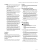
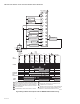
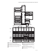
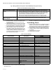
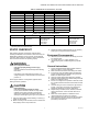
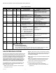
Table Of Contents

RM7898A 7800 SERIES VALVE PROVING PRIMARY RELAY MODULES
66-1161—04 8
Fig. 5. Wiring subbase and sequence chart for RM7898 operating Valve Proving.
Table 2. Recommended Grounding Practices.
9. Maximum wire lengths:
a. RM7898 leadwires: The maximum leadwire length
is 300 feet to terminal inputs (Control, Running/
Lockout Interlock).
b. Flame Detector leadwires: The maximum flame sensor
leadwire length is limited by the flame signal strength.
c. Remote Reset leadwires: The maximum length of wire is
1000 feet (305 meters) to a Remote Reset push button.
d. Data ControlBus™ Module: The maximum Data
ControlBus™ Module cable length depends on the
number of system modules connected, the noise
conditions and the cable used. The maximum length
of all Data ControlBus™ Module interconnecting
wire is 4000 feet (1219 meters).
10.
Be sure loads do not exceed the terminal ratings. Refer to
the label on the RM7898 or to the terminal ratings in Table 3.
Final Wiring Check
1.
Check the power supply circuit. The voltage and frequency
tolerance must match those of the RM7898. A separate
power supply circuit can be required for the RM7898. Add
the required disconnect means and overload protection.
2. Check all wiring circuits and complete Static Checkout
in Table 6 on page 10 before installing the RM7898 on
the subbase.
3. Install all electrical connectors.
4. Restore power to the panel.
Table 3. Terminal Ratings.
a
See Table 2.
b
2000 VA maximum load connected to RM7898 Assembly.
c
See Table 4 and 5.
Ground Type Recommended Practice
Earth ground (subbase and relay
module).
1. Use to provide a connection between the subbase and the control panel of the
equipment. Earth ground must be capable of conducting enough current to blow the
15A, type SC, fast blow fuse (or breaker) in the event of an internal short circuit.
2. Use wide straps or brackets to provide minimum length, maximum surface area
ground conductors. If a leadwire is required, use 14 AWG copper wire.
3. Make sure that mechanically tightened joints along the ground path are free of
nonconductive coatings and protected against corrosion on mating surfaces.
Signal ground (Keyboard Display
Module, Data ControlBus™ Module,
Modbus™ Module.
Use the shield of the signal wire to ground the device to the signal ground terminal 3(c) of
each device. Connect the shield at both ends of the daisy chain to earth ground.
Terminal Number Description
Ratings
RM7898
G Flame Sensor Ground —
Earth G
Earth Ground
a
—
L2(N) Line Voltage Common —
3 Alarm 120 Vac, 1A pilot duty.
4 Burner Motor 120 Vac, 9.8A AFL, 58.8 ALR (inrush).
5 Line Voltage Supply (L1)
120 Vac (+10/-15%), 50 or 60 Hz (±10%).
b
6 or 17 Burner Controller and Limits 120 Vac, 1 mA.
7 Lockout Interlock 120 Vac, 8A run, 43A inrush.
8 Pilot Valve/Ignition
120 Vac
c
9 Main Fuel Valve
120 Vac
c
10 Ignition
120 Vac
c
F(11) Flame Sensor 60 to 220 Vac, current limited.
12 to 15 — Not Used —
16 Valve Proven Pressure Switch Impact 120Vac, 1mA.
17 Demand Input for Valve Proven Feature 120 Vac 1mA.
18 DSI for Valve Proving Enable 120 Vac 1mA.
19 Intermittent Pilot Enable (terminal 8) 120 Vac 1mA.
20 Pre-Ignition Interlock 120 Vac, 1 mA.
21 2nd Stage Main Valve
120 Vac
c
22 Shutter 120 Vac, 0.5A