
Install Instructions


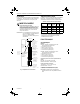
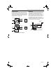
Table Of Contents

95-7232EF.book Page 3 Thursday, February 27, 2003 9:22 AM
RP670A AND B PNEUMATIC SWITCHING RELAYS
Operation Application
When the pilot pressure exceeds the preset spring Fig. 6 shows a typical heating and cooling application
pressure, port 8 opens and connects to port 7 and port 6 using an RP670A. During the cooling cycle, pilot
closes. See Fig. 5A. When pilot pressure is less than the pressure (port 3) is below the relay minimum switching
preset spring pressure, port 8 closes and port 6 opens
and connects to port 7. See Fig. 5B.
RP670A
7
3
A
7
3
SPRING
C
OMMON
PILOT
C
OMMON
PILOT
RP670A
6
8
NORMALLY
CONNECTED
NORMALLY
DISCONNECTED
6
8
NORMALLY
CONNECTED
NORMALLY
DISCONNECTED
A
6
7
8
3
B
6
7
8
3
B
C4287
Fig. 5. RP670 operation.
pressure. Ports 6 and 7 are connected and port 8 is
blocked, removing the low-limit controller from the
system.
During the heating cycle, the pilot pressure is above the
preset switching pressure. Ports 7 and 8 are connected
and the low-limit controller resumes its override
operation. Port 6 is blocked.
THERMOSTAT
DISCHARGE
Fig. 6. RP670A typical application.
M
PILOT
RP670A
13/18 PSI
(
90/125 kPa)
RESTRICTOR
COMMON
M B
NORMALLY
CONNECTED
LOW LIMIT
NORMALLY
DISCONNECTED
COIL
3
8
7
6
C4485
3 95-7232EF–1