
Install Instructions


RP920A,B,C,D MODULAR PNEUMATIC CONTROLLERS
POS.NEG.
5
150
250
300
50
100
Ac (%)
200
POS.
NEG.
C5104
NOTE
LOCATION
OF NOTCH
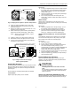
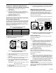
NEGATIVE COMP. (FACTORY SET)
POSITIVE COMP.
DO NOT
ADJUST SCREW
CAPTIVE SCREW (4)
5
150
250
300
50
100
Ac (%)
200
COMPENSATION MODULE
Fig. 5. Changing from negative to positive compensation.
1.
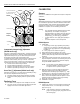
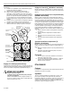
Check the gasket tab position (Fig. 6, front view).
2.
Loosen the three switch block module screws and
remove the module.
3.
Remove the gasket and note the letters (B, B+, C, C+)
embossed on the module back.
4.
Rotate and/or flip the gasket until the gasket position
matches the functions desired (Fig. 6, back view).
NOTE: With the correct gasket position, only the
desired letter shows.
5.
Install the gasket on the switch block module back.
6.
Reinstall the module, and tighten the three screws.
7.
If used, connect the integral action cut-off switching
components to ports 6 and 7.
GASKET SHOWN IN C POSTION. B, B+, AND C+ LEGENDS
7 6 5
40
20
0
60
80
100
%
W
c
C
B
C
+
+
B
CANNOT BE SEEN WITH GASKET IN THE C POSTION,
BUT ARE ILLUSTRATED HERE TO DISLPLAY LOCATION.
C5105
B
C
B
C
+
+
GASKET TAB
IN C POSITION
FRONT
BACK
B
B
+
C
+
C
CAPTIVE SCREW (3)
Switch Block
Fig. 6. Integral action cut-off and gage
function gasket position.
Setpoint (W
1
) Adjustment
The setpoint knob is embossed with a 0 to 100 percent scale
which correlates with the values in Table 3 (see Appendix).
Scaleplate overlays are included to directly match various
sensor ranges.
Three methods of controlling setpoint (W
1
) are available:
LOCAL SETPOINT
Adjust setpoint (W
1
) directly on the controller.
Adjustments:
1.
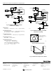
If using a scaleplate overlay, insert the overlay between
the setpoint knob and the transparent overlay retainer.
Note positions of the key and non-coded scaleplate
overlay notch (Fig. 7).
2.
Adjust the setpoint (W
1
), according to the job drawings,
using the setpoint knob.
3.
If the control point deviates excessively from the
setpoint (W
1
), calibrate, taking the throttling range into
consideration.
REMOTE SETPOINT
Setpoint (W
1
) is controlled from 0 to 100 percent of the
primary sensor span from a remote 3 to 15 psi (21 to 103 kPa)
bleed-type signal.
Adjustments:
1.
Adjust the setpoint knob to 100 percent (Fig. 7) or to
the maximum remote setpoint limit to be applied.
2.
Install the 14003755-001 Barb Fitting and O-ring to
port 8 and connect to a bleed-type remote setpoint
device (e.g., SP970) and a remote setpoint gage.
CONTROL POINT ADJUSTMENT (CPA)—AVAILABLE ON SPECIFIC
MODELS
Local (baseline) setpoint (W
1
) is adjusted on the controller
and can be varied ±15 percent of the primary sensor span
from a remote 3 to 15 psi (21 to 103 kPa) signal.
Adjustments:
1.
Pipe CPA to port 9.
2.
If used, select the proper scaleplate overlay.
3.
Note the position of key on the setpoint knob and the
non-coded scaleplate overlay notch (Fig. 7) for
controllers with U.S.A. labels. Controllers (RP920B,C,D)
with German labels must use “R” coded scaleplate
overlay notch when using a CPA device.
4.
Insert the scaleplate overlay between the setpoint knob
and the transparent overlay retainer.
5.
Adjust the setpoint (W
1
) according to the job drawings
using the setpoint knob.
Proportional Band (X
p
) Adjustment
Adjust the proportional band (Xp), according to the job
drawings, using the proportional module proportional band
adjustment knob (see Fig. 2).
CAUTION
Control Loss Hazard.
Loosening knob screws can induce controller
leaks.
Use CCT819 and Authority Setting Adjustment Tool or
a narrow, stiff-blade putty knife to rotate adjustment
knobs (Xp and Ac).
Authority (A
c
) Adjustment (RP920B and D only)
Adjust the authority (A
c
), according to the job drawings, with the
compensation module authority adjustment knob (see Fig. 2).
3 95-7392EF