
Install Instructions


RP920A,B,C,D MODULAR PNEUMATIC CONTROLLERS
CALIBRATION
OVERLAY
RETAINER
Setpoint
Module
LABEL
C5106
20
45
5
10
30
40
Xp (%)
%
20
80
60
40
0
100
W
1
1
1.5
2
3
4
5
7
10
15
20
Min
0.5
TR
DIR. REV. POS. NEG.
250
50
100
RP920
5
150
300
Ac (%)
200
R
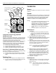
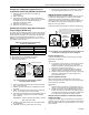
SETPOINT KNOB
SETPOINT
KNOB
KNOB KEY
SETPOINT
NON-CODED
SCALEPLATE
OVERLAY NOTCH
"R" CODED SCALEPLATE
OVERLAY NOTCH
SCALEPLATE OVERLAY
HONEYWELL
Fig. 7. Setpoint (W
1
) Adjustment.
Compensation Startpoint (W
c
) Adjustment
(RP920B and D only)
Adjust the compensation startpoint (W
c
), according to the job
drawings (reset schedule), using the compensation startpoint
adjustment knob (see Fig. 2). For direct-acting sensors, the
knob setting is equal to the compensation value
corresponding to the lowest value given for the primary sensor
(from the reset schedule). See Fig. 9 and 10. If the value
given is not a percentage, convert it to a percentage of the
compensation sensor range using Table 3 (see Appendix):
1.
Find the correct sensor range column.
2.
Find the desired temperature in the column.
3.
Read the equivalent pressure in the second column.
4.
Read the equivalent percentage in the first column.
Reset Time (T
r
) Adjustment (RP920C and D only)
Adjust the reset time (T
r
), according to the job drawings, using
the reset time adjustment knob (see Fig. 2):
1.
Decrease setting until the system becomes unstable.
2.
Increase the setting slightly until the system becomes
stable.
Replacing Cover
1.
If a cover is used, snap the cover straight on the front.
2.
The cover can be secured further by tightening the self-
tapping screw in the cover lower right corner.
Sensors
Sensors are calibrated to the system and require no separate
calibration.
Systems
All RP920 Controllers are factory calibrated. It is intended that
the controller be adjusted to the field-calculated values listed
on the job drawing. This controller startup approach will be
adequate for most systems. If it is determined that closer
calibration is required, use the following procedures:
NOTES:
— The controller allows all adjustments to be made
independently. For example, changing the
proportional band (X
p
) setting does not affect the
calibration of the: setpoint (W
1
), compensation
startpoint (W
c
), or authority (A
c
) adjustment.
— If a CPA device is used, apply 9 psi (62 kPa) to
port 9.
— If a remote setpoint is used, block port 8.
RP920A System
1.
Install either:
a. a temporary receiver gage (matching the primary
sensor) or a 0 to 30 psi (0 to 207 kPa) gage in the
primary sensor gage port if one is not permanently
installed, or
b. a “tee” gage into the sensor line (port 3).
2.
Apply mainline pressure (MLP) to the system.
3.
Install a 0 to 30 psi (0 to 207 kPa) gage in the branchline
pressure (BLP) test tap (moisten the needle before
inserting).
4.
If the sensor reading is greater than ±10 percent of the
expected setpoint, remove the sensor tubing from port 3
and apply a pressure equivalent (expected setpoint)
using a CCT816B Calibration Unit.
NOTE: For the most accurate calibration, the actual
measured variable at the sensor must be
±10 percent of the expected setpoint.
5.
With the sensor at or near the desired control point,
adjust the setpoint knob until the BLP equals the
controlled device throttling range midpoint, e.g., 8 psi
(55 kPa) for a 3 to 13 psi (21 to 90 kPa) range device.
6.
If the setpoint (W
1
) and primary sensor gage do not
match, remove the setpoint knob and replace it so the
setpoint matches the primary sensor gage reading.
7.
Ensure W
1
is at the desired setpoint.
8.
Calibration is complete.
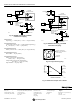
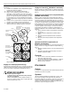
RP920B Systems
1.
Install in port 5 either a receiver gage that matches the
compensation sensor, or a 0 to 30 psi (0 to 207 kPa)
gage (see Fig. 8).
NOTE: If the controller is setup for a compensation
gage in the right gage port, plug port 5 and use
the existing gage.
95-7392EF 4