
Install Instructions


RP920A,B,C,D
Modular Pneumatic Controllers
INSTALLATION INSTRUCTIONS
INSTALLATION
Adjustments Before Mounting
1.
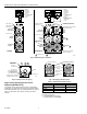
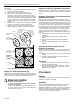
If a connection to port 4, 6, 7, or 8 (Fig. 2) is required,
remove the self-tapping screw from port 8 and use the
screw to tap the appropriate port.
2.
Install 14003755-001 Barb Fitting and O-ring finger-tight
in the appropriate port.
3.
Reinstall the screw in port 8 if not used.
4.
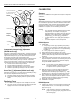
If a remote restriction is used for the primary sensor,
block the internal air supply (adjustable after gage
installation, but easier to adjust before installation):
a. Loosen the screw one turn (Fig. 3) and rotate the
switchplate (light grey) 90 degrees counterclockwise
to the sensor supply blocked position.
b. Retighten the screw and check for leaks. If a leak is
found, reposition the switchplate.
NOTES:
— The switchplate screw must be tightened securely
to prevent a false inoperative sensor condition.
— The compensation sensor on port 5 requires an
external restricted main air supply.
Device Mounting
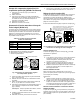
1.
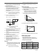
Mark and drill two No. 8 fastener mounting holes using
the controller or Fig. 1 dimensions as a template.
2.
Mount the controller with two No. 8 fasteners (not
supplied).
Connections
1.
Push the tubing on the port barb fittings according to
the job drawings. See Fig. 2 for port locations.
2.
Install the gage or plug:
a. If no gage is used, tighten gage plugs finger-tight.
If a gage is used, remove the plug and, by hand,
screw the gage into the gage port three turns.
b. If the gage is not oriented for correct viewing, rotate
the gage counterclockwise until correct.
NOTE: A soft-rubber, factory-installed seal allows
plug or gage rotation (for alignment) without
leakage.
3 (75) MINIMUM CLEARANCE
4
(102)
3-3/8 (86)
9/32
(7)
RP920A: 1-1/2 (36)
RP920B-D: 3-1/4 (83)
5-7/8
(148)
1/8 (3)
MINIMUM
SPACING
BETWEEN
MODULES
RP920A: 1-7/8 (48)
RP920B-D: 3-13/16 (96)
M17581
Fig. 1. RP920 Dimensions in in. (mm).
After Mounting Adjustments and Changes
Controller Action Change
1.
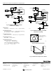
Loosen the four Proportional Module screws (Fig. 4).
2.
Remove the module.
3.
Rotate the module and its gasket 180 degrees, and
reinstall. Ensure that the notch on the module lines up
with the proper indication on the controller label (base).
4.
Retighten the four screws.
5.
Recalibrate if required.
Negative (Winter) to Positive (Summer)
Compensation Change (RP920B and D only)
1.
Loosen the four compensation module screws (Fig. 5).
2.
Remove the module.
3.
Rotate the module and its gasket 180 degrees, and
reinstall. Ensure that the notch on the module lines up
with the proper indication on the controller label (base).
4.
Retighten the four screws.
5.
Recalibrate, if required.
® U.S. Registered Trademark
Copyright © 2000 Honeywell • All Rights Reserved
95- 7392EF