
Install Instructions
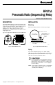

RP971A PNEUMATIC RATIO (SEQUENCING) RELAY
ENGINEERING DATA
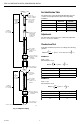
Specifications
Model:
RP971A Pneumatic Ratio (Sequencing) Relay
❑ 3 psi (21 kPa) pilot span
❑ 5 psi (90 kPa) pilot span
Operating Pressure (Switch and Pilot) Range:
Normal Main: 118 psi (124 kPa)
Maximum Safe Main: 30 psi (207 kPa)
Pilot: 0 to 18 psi (21 to 124 kPa)
Operating Limits:
Temperature: 0 to 140AF (-18 to 60AC)
Relative Humidity: 5 to 95%
Air Handling Capacity (Feed and Bleed):
0.039 scfm at E 1.02 psi droop (18.3 ml/sec at 7 kPa
droop). Conditions: 18 psi (124 kPa) Main and 9 psi
(62 kPa) Pilot
Air Consumption:
0.002 scfm (1.0 ml/s) maximum
Start Point:
Adjustable 0 to 10 psi (0 to 69 kPa)
RP971A
Construction:
Molded plastic with neoprene diaphragm, stainless
steel valve seats, and 100-mesh stainless steel
filters in main and branch ports
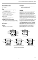
Operation
The effective area ratio between the pilot and feedback
diaphragms controls the ratio between the pilot and
branchline pressures. Fig. 4 shows a cutaway of typical
operation. Exhaust Port 4 is not used. The 3 psi (21 kPa)
model gives a 10 psi (69 kPa) variation in branchline
pressure for a 3 psi (21 kPa) change in pressure. The start
adjustment sets pilot pressure at the point where branchline
pressure begins to increase above 3 psi (21 kPa.) For
example, a 5 psi (34 kPa) setting outputs 3 psi (21 kPa) with
a 5 psi (34 kPa) pilot signal.
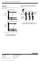
Fig. 4A shows the RP971A in a balanced condition. As pilot
pressure increases, the exhaust tube lifts Diaphragm 1,
feeding main air into the branch chamber (Fig. 4B) through
small holes in the diaphragm. This pressure pushes down
on the feedback diaphragm and retracts the exhaust tube,
which returns the relay to a balanced condition (Fig. 4C.)
When pilot pressure drops, the exhaust tube retracts further
and bleeds the branchline air into the atmosphere (Fig. 4D.)
When sufficient air has bled off, the relay returns to a
balanced condition with a new and lower branchline
pressure (Fig. 4E.)
RP971A
MAIN
D. REDUCED PILOT EXHAUSTING BRANCH
PILOT
PILOT
PILOT
DIAPHRAGM
DIAPHRAGM 1
A. BALANCED CONDITION
B. PILOT CALLING FOR INCREASED OUTPUT
EXHAUST
PORT
BRANCH
CHAMBER
1
3
BRANCH
EXHAUST
TUBE
FEEDBACK
DIAPHRAGM
START
SPRING
MAIN
2
4
PILOT
1
3
BRANCH
RP971A
2
4
PILOT
EXHAUST
PORT
1
3
BRANCH
MAIN
RP971A RP971A
3
4
2
4
PILOT
EXHAUST
PORT
1
3
MAIN
2
4
1
BRANCH
MAIN
2
BRANCH
EXHAUST
PORT
C. BALANCE CONDITION E. BALANCED CONDITION
C4502
Fig. 4. Typical RP971A Operation.
3
95-7234