
Specification Sheet


RETROFIT ROUND DAMPER (RRD)
3 69-1960ES—01
INSTALLATION
Before Installing this Product
1. Read all instructions before installing this product. Fail-
ure to follow instructions can damage the product or
cause a hazardous condition.
2. Check the ratings given in the instructions and on the
product to verify that the product is suitable for your
application.
3. Installer must be a trained and experienced service tech-
nician.
4. Install the product in an area that is easily accessible for
checkout and service.
5. After completing installation, use these instructions to
check out product operation.
Installing the Retrofit Round Damper
Select a location for the damper in the ductwork. It is
suggested that the RRD damper be at least 6 feet from the
register for quiet operation.
1.
Peel off the back of the cut-out template. Carefully align
the template with the centerline of the duct. Apply tem-
plate to the section of round ductwork where the damper
is to be installed. Ensure that the template is parallel to
the ductwork. It is suggested that the damper be installed
with the motor under a horizontal duct to reduce twist to
the duct. It may also be necessary to support the duct.
2. Drill a starter hole in the cut-out area of the template.
3. Cut out the area between the holes.
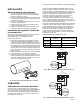
4. Slide the damper into the duct and secure it with the four
supplied self-drilling mounting screws. Be careful to
avoid over-tightening the screws as the duct may be
pulled out of round. See Fig. 3.
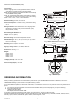
Fig. 3. Inserting RRD damper into duct.
WIRING
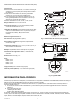
Wiring the Motor Actuator
Connect the motor to the zone control panel 18 or 20 gauge
wire. The motor terminals are labeled M1 for common, M4 for
open, and M6 for closed. Connect the motor terminals to
corresponding terminals on zone control panel for each zone.
See Fig. 4–6 for hookups.
Multiple RRD dampers can be wired to one zone when wired in
parallel. See Fig. 5 for wiring multiple dampers together in a
daisy chain manner or Fig. 6 using wire nuts. See Table 1 for
the maximum number of dampers that can be connected to
each zone control panel. Note that this is the total number of
dampers connected to all the zones of a zone control panel;
the maximum dampers per zone is 14. If more than 14
dampers are on one zone, a Slave Damper Control Relay
(SDCR) must be used.
When more than the maximum number of dampers allowed
per panel are necessary, a SDCR must be used. The SDCR is
an isolation relay that is powered by a separate transformer so
that it relieves the panel of this additional load. When a SDCR
is used, the dampers of that zone may either be all connected
to the SDCR, or some dampers may be wired to the SDCR and
the remainder to that zone’s damper terminals.
*Maximum of 14 dampers per zone
Fig. 4. RRD wired to zone control panel.
Fig. 5. Wiring multiple RRD dampers in
daisy chain fashion.
M31220
Maximum number of dampers per zone.
One 40 VA
Transformer
Two 40 VA
Transformers (or
One 75 VA)
TrueZONE® Panels* 13 27
W8835* 12 26
SDCR 15 28
RYWGCM6M4M1
RYWG
ZONE
1, 2, 3, ETC.
M1
M4
M6
M31217
ZONE
THERMOSTAT
R Y W G C M6 M4 M1
R Y W G
ZONE
1, 2, 3, ETC.
M 1
M 4
M 6
M1
M4
M6
M31218
ZONE
THERMOSTAT