
RRD Spec Sheet
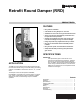
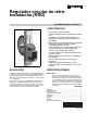

RETROFIT ROUND DAMPER (RRD)
Automation and Control Solutions
Honeywell International Inc.
1985 Douglas Drive North
Golden Valley, MN 55422
Honeywell Limited-Honeywell Limitée
35 Dynamic Drive
Toronto, Ontario M1V 4Z9
customer.honeywell.com
® U.S. Registered Trademark
© 2010 Honeywell International Inc.
69-1960ES—01 E.K. Rev. 02-10
Printed in U.S.A.
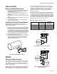
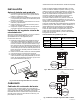
Fig. 6. Wiring multiple RRD dampers using wire nuts.
ADJUSTMENTS
Manual Blade Adjustment
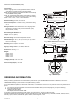
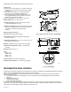
To verify correct range of motion, depress the manual blade
adjustment button. While this is pressed, the gears are
disengaged, allowing the blade to be manually opened or
closed by turning the damper blade shaft. See Fig. 1.
Position Indicator
The position indicator (shown in Figure 1) points toward the
position of the damper blade to identify if the blade is open,
closed, or at an intermediate position. A slot at the end of the
damper blade shaft also indicates blade position.
Range stops
The RRD damper motor can be adjusted to prevent complete
closure of the blade. This is useful in zone systems where it is
not possible to install a bypass damper.
To set the range stop to prevent complete closure:
1. Locate the range stop adjustment screw on the top of
the motor to the right blade shaft. This is at the extreme
counter-clockwise end of travel.
2. Using a small Phillips head screwdriver, loosen the
set screw.
3. Move the end-stop block to the new position
4. Secure the set screw.
5. Verify the new range of motion while depressing the
manual blade release button.
Rotation Direction Adjustment
The rotation direction screw (Shown in Figure 1) reverses the
direction the damper operates. It should be left in the "0"
position to open when M4 is powered and close when M6 is
powered.
CHECKOUT
CAUTION
Possible Equipment Damage
Do not manually open or close the damper unless the
manual blade release button is depressed.
To check out the RRD damper using 24 VAC transformer:
1. Connect 24 VAC common to the M1 (common) terminal
on the actuator.
2. Connect 24 VAC hot to the M6 terminal to close
the damper.
3. Observe the blade move clockwise and stop in the
closed position.
4. Remove the 24 VAC hot wire from the M6 terminal.
5. Connect the 24 VAC hot wire to the M4 terminal.
6. Observe the blade move counter-clockwise and stop in
the open position.
7. This verifies correct operation.
Alternatively, if the damper is wired to a TrueZONE HZ432 or
HZ322 panel, the damper checkout process may be used to
verify damper operation.
TROUBLESHOOTING
R Y W G C M6 M4 M1
R Y W G
ZONE
1, 2, 3, ETC.
M1
M4
M6
M1
M4
M6
M31219
ZONE
THERMOSTAT
WIRE NUT
Damper operates backwards Verify correct damper wiring as shown in Fig. 4–6. Also verify that the Rotation
Direction screw is in the "0" position as shown in Figure 1.
Damper does not operate 1. Verify damper wiring using checkout methods listed in this document.
2. Verify that the duct is round and not making the blade stick. Depress the
manual blade release button and manually turn the blade shaft to verify
smooth opening and closing operation.