
Specification Sheet

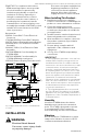

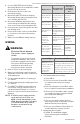
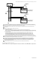

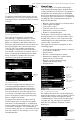
Table Of Contents

7800 SERIESS7800A2142 4Line LCD Keyboard Display Module
5 320011007
1. Use the 203765 Remote Display
Mounting Bracket as a template to mark
the four screw locations.
2. Drill the pilot holes for the four
mounting screws.
3. Mount the 203765 Remote Display
Mounting Bracket by securing the four
no. 6 screws (M3.5 x 0.6).
4. Mount the KDM by aligning the two
interlocking ears with the two mating
slots on the remote mounting bracket.
5. Insert the two interlocking ears into the
two mating slots.
6. Push on the lower corners of the KDM
to secure it to the remote mounting
bracket.
7. Make sure the KDM is firmly in place.
WIRING
WARNING
Electrical Shock Hazard.
Can cause severe injury or
death.
To prevent electrical shock and
equipment damage, disconnect
the power supply from the main
disconnect before beginning
installation. More than one
disconnect can be involved.
1. Refer to Fig. 3 for proper wiring.
2. Make sure all wiring complies with all
applicable electrical codes, ordinances
and regulations.
3. For recommended wire size and type,
see Table 1.
4. For Recommended grounding practices,
see Table 2.
5. For KDM: The KDM is powered from a
low voltage, energy- limited source. It
can be mounted outside of a control
panel if it is protected from mechanical
damage.
NOTE: A 13 Vdc power supply must be
used any time more than one
KDM is used. A maximum of two
KDM, Data ControlBus™ Modules
or S7810B Multi-Drop Switch
Modules are allowed in any
combination.
Application
Recommend-
ed Wire Size
Recom-
mended
Part Num-
ber
Keyboard Dis-
play Module
22 AWG two-
wire twisted pair
with ground, or
five-wire.
Belden 8723
shielded
cable or
equivalent.
Data Control-
Bus™ Module
22 AWG two-
wire twisted pair
with ground, or
five-wire.
Belden 8723
shielded
cable or
equivalent.
Remote Reset
Module
22 AWG two-
wire twisted pair,
insulated for low
voltage.
—
Commu-
nications
Interface
ControlBus
Module™
22 AWG two-wire
twisted pair with
ground.
Belden 8723
shielded
cable or
equivalent.
13 Vdc full
wave rectified
transformer
power input.
18 AWG wire,
insulated for
voltages and
temperatures for
given applica-
tions.
TTW60C,
THW75C,
THHN90C
Table 1. Recommended Wire Size and Part Number.
Ground Type Recommended Practice
Signal ground
(KDM, Data Con-
trolBus™ Module,
Communica-
tions Interface
ControlBus
Module™).
Use the shield of the signal
wire to ground the device to
the signal ground terminals
[3(c)] of each device. Con-
nect the shield at both ends
of the daisy chain to ground.
Table 2. Recommended Grounding Practices.
6. Recommended wire routing:
a. ControlBus:
(1) Do not route the ControlBus cable
in conduits that carry line voltage
circuits.
(2) Avoid routing the ControlBus cable
close to ignition transformer leadwires.
(3) Route the ControlBus cable outside
of conduit if properly supported and
protected from damage.
b. Remote Reset:
(1) Do not run high voltage ignition
transformer wires in the same conduit
with the Remote Reset wiring.
(2) Do not route Remote Reset wires in
conduit with line voltage circuits.
7. Maximum wire lengths:
(a) KDM: The maximum length
interconnecting wire is 4000 ft
(1219m).