
Product Overview

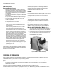
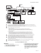
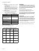
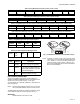
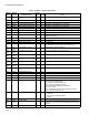
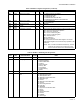
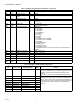
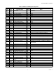

Table Of Contents

S7810M MODBUS™ MODULE
65-0249—07 4
4. Wire routing:
a. Do not route the communication cable in conduit with
line voltage circuits.
b. Do not route the communication cable close to the
ignition transformers.
c. Route the communication cable outside of conduit if
properly supported and protected from damage.
d. Route the communication cable so that all devices
are connected in a daisy chain configuration. See
Fig. 3.
5. Maximum wire lengths:
a. Communications bus, 4000 feet (1219 meters).
b. Remote reset switch, 1000 feet (305 meters).
Table 1. S7810M Terminal Identification.
MODE LED Light Patterns
Table 2 explains the MODE LED light patterns.
OPERATION
The S7810M ModBus™ Data ControlBus™ Module has two
communications ports. The ControlBus™ communications port
allows communications on a bus that contains a 7800 SERIES
burner controller and an S7800 Keyboard Display Module and/
or an S7830 Expanded Annunciator and/or an R7999
ControLinks™ Controller.
A second communications port supports RS-485
communications using ModBus™
protocol. The following
tables provide ModBus™ mapping information.
Table 10 provides register mapping. It identifies the mapping of
the 7800 SERIES parameters to ModBus™ registers. These
codes are transmitted by the relay modules and the S7830
Expanded Annunciator.
Function Codes
Supported function codes of ModBus™ Protocol Reference
Guide (PI-MBUS-300 Rev. J) are 3, 4, 6, and 17. Function
codes 3 and 4 are treated the same by the S7810M. Two
registers need to be read when the data format is a U32 value
(4 bytes); if both registers are not read, then a data value of 0
(zero) is returned. U32 values are in little endian format. The
maximum number of addresses that can be queried is 127
(0x7F) for query messages 3 and 4.
Tables 3 through 7 provide information on the function codes.
NOTE: All Query and Response cells below are 1 byte.
Signal S7810M Terminal
ControlBus™ Data + 1
ControlBus™ Data - 2
Common
• ControlBus™ Common
• +13 Vdc Common
• Remote Reset Common
3
+13 Vdc 4
Remote Reset 5
ModBus™ Common 6
ModBus™ Data + 7
ModBus™ Data - 8
Table 2. Explanation of MODE LED light patterns
LED Code/
Behavior Pulse Period Interval Meaning
Always OFF OFF Not powered or
device failure.
Always ON ON S7810M device
failure.
Mostly ON
with 1 blink
50 ms (OFF) 1 second Both ControlBus™
and ModBus™ are
active
Mostly OFF
with 1 flash
50 ms (ON) 3.85
seconds
ControlBus™ is
active, and
ModBus™ is not
active.
Mostly OFF
with 2
pulses
2 x (200 ms
ON, 200 ms
OFF)
1.75
seconds
Program CRC
error.
Mostly OFF
with 3
pulses
3 x (200 ms
ON, 200 ms
OFF)
2.15
seconds
No ControlBus™
signal from the
Burner Control