
S9200U Installation Guide
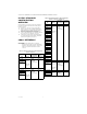
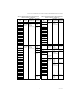
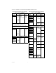
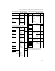
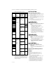
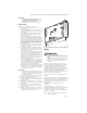

Table Of Contents
- Application
- Features
- Specifications
- Installation and Configuration Overview
- Cross Reference
- Installation
- Safety Timings, Field Settings, and Fixed Parameters
- Thermostat Type
- Twinning
- Checkout
- I. Check Normal Operation
- II. Check Safety Shutoff Operation
- Troubleshooting
- Application
- CARACTÉRISTIQUES
- SPÉCIFICATIONS
- APERÇU DE L'INSTALLATION ET DE LA CONFIGURATION
- CORRESPONDANCES
- Installation
- TEMPORISATIONS DE SÉCURITÉ, RÉGLAGES DE COMMUTATEUR SUR SITE ET DE PARAMÈTRES FIXES
- TYPE DE THERMOSTAT
- PAIRAGE
- VÉRIFICATION
- I. VÉRIFICATION DU FONCTIONNEMENT NORMAL
- II. VÉRIFICATION DE LA COUPURE DE SÉCURITÉ
- DÉPANNAGE

S9200U1000 UNIVERSAL HOT SURFACE IGNITION INTEGRATED FURNACE CONTROL
69-2075EF—05 6
INSTALLATION
When Installing This Product…
1. Read these instructions carefully. Failure to fol-
low them could damage the product or cause a
hazardous condition.
2. Check the ratings given in these instructions to
make sure the integrated furnace control is suit-
able for your application.
3. Installer must be a trained, experienced service
technician.
4. After installation is complete, check out opera-
tion as provided in these instructions.
WARNING
Fire or Explosion Hazard.
Can cause severe injury, property damage, or
death.
1. The integrated furnace control can
malfunction if it gets wet, leading to
accumulation of explosive gas.
— Never install where water can flood, drip or
condense on the control.
— Never try to use an integrated furnace
control that has been wet—replace it.
2. Liquefied petroleum (LP) gas is heavier than
air and will not naturally vent upward.
— Do not operate electric switches, lights, or
appliances until you are sure the appliance
area is free of gas.
WARNING
Electrical Shock Hazard.
Can cause severe injury, property damage, or
death.
1. Make sure to turn power off to the furnace.
Failure to do this may result in electrical
shock or equipment damage
2. Disconnect power supply before beginning
wiring or making wiring connections to
prevent electrical shock or equipment
damage.
CAUTION
Equipment Damage Hazard.
Water can cause equipment damage or
malfunction.
If furnace control must be mounted near water
or moisture, provide suitable waterproof
enclosure.
Replacing An Existing Furnace
Control
Location
In most cases the integrated furnace control is
mounted on a panel within the circulator
compartment of the furnace. The location must
provide:
— Access to the field wiring terminals.
— Operating ambient temperatures between -40°F
and 175°F (-40°C and 79°C).
— Relative humidity below 95% non-condensing.
— Protection from water, steam or corrosive
chemicals that are used to clean the appliance.
— Protection from dripping water, such as from an
overfilled humidifier or from condensation.
— Protection from dust or grease accumulation.
Table 2. Replacing Trane Controls.
SKU Harness
Field Settings
Recommenda
tion - DIP
Switch S1
Safety
Timing
Settings -
DIP
Switch S2
Trane
CNT1309 Add jumper on
harness
connector
(Roll-out
switch)
A
Inducer & HSI
Connector
SW1: Check
Settings
SW2: ON
SW3 & SW4:
60/90/120/180
SW1: OFF
SW2: ON
CNT1616
CNT1848
CNT1849
CNT2182
CNT2183
CNT2181
CNT2789
CNT03740 SW1: ON
SW2: OFF
SW3 & SW4:
60/90/120/180
SW1: OFF
SW2: OFF
D330927P01
D330930P01 SW1: OFF
SW2: OFF
SW3 & SW4:
60/90/120/180
SW1: OFF
SW2: ON
D330934P01
D340035P01
D340354P01
D340774P01
D340790P01 SW1: Check
Settings
SW2: ON
SW3 & SW4:
60/90/120/180
SW1: OFF
SW2: OFF
D341122P01
D341235P01 SW1: ON
SW2: OFF
SW3: ON
SW4: OFF
White Rogers
50A50-571 Add jumper on
harness
connector
(Roll-out
switch)
A
Inducer &
HSI
Connector
SW1: ON
SW2: OFF
SW3 & SW4:
60/90/120/180
SW1: OFF
SW2: OFF
50A55-571 SW1: OFF
SW2: OFF
SW3: ON
SW4: OFF
50A50-473 SW1: OFF
SW2: OFF
SW3 & SW4:
60/90/120/180
SW1: OFF
SW2: ON
50A50-474
50A50-405
50A50-406
50A50-471
50A55-474 SW1: OFF
SW2: OFF
SW3: ON
SW4: OFF
SW1: OFF
SW2: OFF
50A55-438 SW1: Check
Settings
SW2: OFF
SW3 & SW4:
60/90/120/180
SW1: OFF
SW2: OFF
NOTE: To replace controls in Table 2, a jumper
(included with harness kit) may be required
to short out the rollout switch on the main
12-pin connector plug from the furnace. The
rollout switch is located between pins 5 and
11 on the 12-pin connector. Refer to Table 3
and Fig. 2 on page 8.