
S9200U Installation Guide
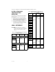
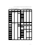
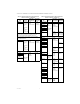
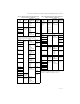
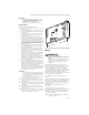
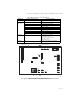

Table Of Contents
- Application
- Features
- Specifications
- Installation and Configuration Overview
- Cross Reference
- Installation
- Safety Timings, Field Settings, and Fixed Parameters
- Thermostat Type
- Twinning
- Checkout
- I. Check Normal Operation
- II. Check Safety Shutoff Operation
- Troubleshooting
- Application
- CARACTÉRISTIQUES
- SPÉCIFICATIONS
- APERÇU DE L'INSTALLATION ET DE LA CONFIGURATION
- CORRESPONDANCES
- Installation
- TEMPORISATIONS DE SÉCURITÉ, RÉGLAGES DE COMMUTATEUR SUR SITE ET DE PARAMÈTRES FIXES
- TYPE DE THERMOSTAT
- PAIRAGE
- VÉRIFICATION
- I. VÉRIFICATION DU FONCTIONNEMENT NORMAL
- II. VÉRIFICATION DE LA COUPURE DE SÉCURITÉ
- DÉPANNAGE

S9200U1000 UNIVERSAL HOT SURFACE IGNITION INTEGRATED FURNACE CONTROL
7 69-2075EF—05
IMPORTANT
Be sure to identify the safety timings on the
existing furnace control before any wires are
disconnected. If this information is
unavailable, check with the furnace
manufacturer for recommended settings.
Replacement
To replace the existing furnace control:
1. Remove the access panel to gain access to the
furnace control.
2. Unclip the wiring harness from the furnace con-
trol and identify/mark all wires not connected to
a wiring plug.
3. Once the furnace control is free from all wiring,
either unclip or unscrew the furnace control
from the base plate.
4. Select the location within the appliance most
suitable so that all existing cables or required
harnesses will reach without straining either the
cables or the plugs. We recommend mounting
the S9200U1000 in the same location as the old
furnace control, if possible. Ambient tempera-
ture at the S9200U1000 must be within the con-
trol specifications.
5. The S9200U1000 can be mounted vertically in
any orientation. See Fig. 4 on page 9 for typical
mounting orientation.
6. Secure the board to the mounting panel base
plate with the two sheet metal screws inserted
through the eyelets located on the edges of the
board. See Fig. 1 on page 7.
7. From Table 1 on page 2, identify the wiring har-
ness(es) required for the quick installation of the
S9200U1000. The provided wiring harness
adapters are intended to connect to the existing
wiring harness. See Table 3 on page 8 and
Table 4 on page 8 for pin-out information for the
provided wiring harnesses.
8. Connect the appropriate end of the wiring har-
ness to the 12-pin plug on the S9200U1000 (if
required) and the other end to the existing wiring
plug (previously removed from the existing fur-
nace control). Connect the appropriate
igniter/inducer harness (if required) to the 4 pin
plug and the other end to either the existing plug
or spade connectors (previously removed from
the existing furnace control).
IMPORTANT
The provided wiring harnesses are keyed. Do
not force the connection if the plug on the har-
ness and receptacle on the S9200U1000 do
not easily snap closed.
9. Connect the quick-connect cables to the appro-
priate contacts on the S9200U1000
10. Set the Safety timings as required using switch
S2. Refer to Table 10 on page 12 for switch set-
ting information.
11. Set the field selectable timings as required using
switch S1. Refer to Table 9 on page 11 for setting
information.
12. Review the connections to insure no wiring is
loose and there is a proper earth ground to the
appliance chassis.
13. Turn power ON to the appliance. See “Checkout”
on page 13 and the control sequence diagrams,
Fig. 9-Fig. 11 beginning on page 18.
Fig. 1. S9200U1000 dimensions in inches and (mm).
Wiring
WARNING
Fire or Explosion Hazard.
Can cause severe injury, property damage, or
death.
Make sure the proper wiring harness is used.
Check the cross reference tables (Table 1 on
page 2) and review the appliance wiring
schematic.
The S9200U1000 is intended to connect to the
appliance with the aid of wiring harnesses. Carefully
review the wiring harness selection table for the
correct wiring harnesses. See Table 1 on page 2.
Check the wiring diagram (Fig. 4 on page 9) and the
diagram furnished by the appliance manufacturer for
all terminal designations. Table 5 and Table 6
beginning on page 8 describe the wiring connections
for Class 2 and Class 1 installations.
Typical wiring connections are shown in Fig. 5 on
page 10.
Check the wiring diagrams furnished by the appliance
manufacturer, if available, for circuits that differ from
the general hookup shown. Carefully follow any
special instructions affecting the general procedures
outlined below.
All wiring must comply with local codes and
ordinances.
See “Wiring Harnesses” for the main and
igniter/inducer harness plug connections and details.
See “Wiring Connections” on page 8 for wiring
connections, but also refer to furnace manufacturer
instructions, if available.
NOTE: The Safety Timing jumper is described in
Table 7 on page 11.
4 1/8
(105)
1 1/2
(38)
6 1/8
(156)
M24905