
S9200U Installation Guide
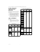
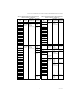
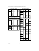
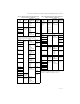
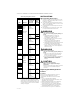
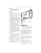
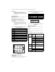
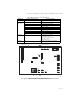

Table Of Contents
- Application
- Features
- Specifications
- Installation and Configuration Overview
- Cross Reference
- Installation
- Safety Timings, Field Settings, and Fixed Parameters
- Thermostat Type
- Twinning
- Checkout
- I. Check Normal Operation
- II. Check Safety Shutoff Operation
- Troubleshooting
- Application
- CARACTÉRISTIQUES
- SPÉCIFICATIONS
- APERÇU DE L'INSTALLATION ET DE LA CONFIGURATION
- CORRESPONDANCES
- Installation
- TEMPORISATIONS DE SÉCURITÉ, RÉGLAGES DE COMMUTATEUR SUR SITE ET DE PARAMÈTRES FIXES
- TYPE DE THERMOSTAT
- PAIRAGE
- VÉRIFICATION
- I. VÉRIFICATION DU FONCTIONNEMENT NORMAL
- II. VÉRIFICATION DE LA COUPURE DE SÉCURITÉ
- DÉPANNAGE

S9200U1000 UNIVERSAL HOT SURFACE IGNITION INTEGRATED FURNACE CONTROL
69-2075EF—05 8
IMPORTANT
The common ground required for the
S9200U1000 and the main burner must be
supplied through the plug connected to the
Main Harness (12-pin connector) receptacle
on the board.
Wiring Harnesses
The following describes the main and igniter/inducer
harness connections.
MAIN HARNESS PLUG CONNECTIONS
The following describes the harness plug connectors
for the main harness. See Table 3 and Fig. 2.
IMPORTANT
The common ground required for the
S9200U1000 and the main burner must be
supplied through the plug connected to the
Main Harness (12-pin connector) receptacle
on the board.
1
Utilize 12x12 32339640-001 Harness (H) when Fur-
nace Harness Pressure Switch Out I/O is located on
Pin 4 and not on Pin 7.
Fig. 2. S9200U1000 Main harness plug
configuration.
IGNITER/INDUCER HARNESS PLUG
CONNECTIONS
The following describes the harness plug connectors
for the igniter/inducer. See Table 4 and Fig. 3.
.
Fig. 3. S9200U1000 Igniter/Inducer harness plug
configuration.
Wiring Connections
Table 5 describes the wiring connections for Class 2
voltages.
Table 6 describes the wiring connections for Class 1
voltages.
See Fig. 5 on page 10 for wiring connection locations
on the board.
Table 3. Main Harness Plug Connector 12-pin
(Class 2, Low Voltage).
Pin # Function
1High Limit Out
2 Flame Sense - Flame Signal Input (90 Vac, current limited)
3 24 Vac Hot
4
Not Used
1
5 Rollout Switch Out
6 24 Vac Common
7 High Limit In + Pressure Switch Out
8 Chassis Ground
9Main Valve Common
10 Pressure Switch In
11 Rollout Switch In
12 Main Valve
1 4 7 10
2 5 8 11
3 6 9 12
M24906
Table 4. Igniter/Inducer Harness Plug Connector 4-
pin
(Class 1, Line Voltage).
Pin # Reference Lettering Function
1 IND-HOT Inducer 120 Vac
2 IGN-HOT Igniter 120 Vac
3 IND-NEUTRAL Inducer Neutral
4 IGN-NEUTRAL Igniter Neutral
Table 5. Wiring Connections (Class 2, Low Voltage).
Terminal Type
Connection
(see Fig. 4
on page 9) Connects S9200U1000 to:
6-position
screw terminal
(#5 screw)
D/1
(optional)
EnviraCOM™ data connection (if used)
C/3 24 volt ground
R/2 24 volt hot - Thermostat
W Thermostat heat input
G Thermostat continuous fan input
Y Thermostat cool input / cooling
contactor output for EnviraCOM™
thermostats
Polarized 3-
pin connector
E-COM EnviraCOM™ diagnostic or
communications device
12-pin
connector
Main
Harness
Connector
See Table 3 on page 8
Straight Spade
Quick-connect
24 Vac Transformer - 24 Vac
COM Transformer - Common
Fuse Block Fuse Fuse - Automotive Type - 3.0 Amps
4 3 2 1
M24907