Heating Controller SDC Remote Heating Controller DHC OPERATING INSTRUCTIONS EN2H-0220GE51 R0308
EN2H-0220GE51 R0308
SDC / DHC Contents Contents 1 Software version ............................................................................................................. 7 2 Safety instructions.......................................................................................................... 7 2.1 Intended use ........................................................................................................ 7 2.2 Requirements for start-up .............................................................
Contents SDC / DHC 4.2.1 "Time - Date" menu ............................................................................... 33 4.2.2 "Timeprograms" menu .......................................................................... 34 4.2.2.1 Selection of the control circuit ................................................. 35 4.2.2.2 Selection of the program ......................................................... 35 4.2.2.3 Selection of day of the week and cycle ................................... 35 4.
SDC / DHC EN2H-0220GE51 R0308 Contents 5
SDC / DHC Software version Pos: 1 /156-Honeywell/Softwareversion/Softwareversion @ 0\m od_1207134342657_6.doc @ 9090 1 Software version This documentation is valid for software version V 3.0 of your control device. The software version is displayed after switch-on for approx. 8 s. If you are using an older software version, please contact your heating technician. Pos: 2 /156-Honeywell/Sicherheitshinweise/Sicherheitshinweise @ 0\mod_1207134414454_6.doc @ 9105 2 2.
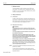
Safety instructions SDC / DHC 2.2.1 Power supply Do not disconnect the controller from the mains supply! The battery for saving all individualised data is otherwise unnecessarily strained. The frost-protection function of the controller is deactivated. 2.2.2 Connection conditions All electrical connection work may only be carried out by qualified personnel! 2.2.3 Cable cross-sections 1.5 mm2 for all cables carrying 230 V (power supply, burner, pumps, actuator). 0.
SDC / DHC Safety instructions 2.2.6 Grounding and zeroing Local regulations on the connection of equipment must be observed! 2.3 Hot-water temperature greater than 60 °C ATTENTION Note that there is a danger of scalding at all hot-water drawoff points (kitchen, bathroom etc.) in the following cases. Add sufficient cold water in these cases.
Safety instructions SDC / DHC 2.4 Connection of accessory parts WARNING According to VDE 0730, a separator for each mains terminal is to be provided in the voltage supply to the control equipment. Observe the local regulations regarding grounding and zeroing. As soon as the mains voltage is applied to terminals 21, 22, 2, 6, 12 and 18, headers X3 and X4 can also carry mains voltage.
SDC / DHC Overview 3 Overview x SDC 3-40 3 – – – x – – – – SDC 7-21 1) 7 – x x x – x – – x x x – x x x SDC 9-21 2) 7 x + two variable relays x x x x x x x SDC 12-31 3) 10 x + two variable relays 1) DHC 43-1 2) DHC 43-2 3) DHC 43-3 Variable output 2 Variable output 1 – Tank loading pump Mixed heating circuit 2 – Variable output 3 x Direct heating circuit x Burner stage 1 – District heating valve CLOSED 3 or SDC 3-10 Type Burner stage 2 Mixed h
Operation SDC / DHC 4 4.
SDC / DHC Operation 4.1.1 Display (basic display) 1 C 2 3 4 5 1 Day of the week / Date 4 Operating mode symbols 2 Time 5 Heat generator temperature 3 Active operating mode The illumination of the display is switched on by pressing any button or using the input button î and switches off automatically if no buttons are pressed for a longer period of time. During start-up of the unit and after a power failure, a segment test with automatic fault diagnosis is carried out.
Operation SDC / DHC 4.1.2 Operating elements Pos: 7 /156-Honeywell/Bedienung/Eingabeknopf @ 1\m od_1207643768135_6.doc @ 9240 4.1.2.1 Input button (press / turn) ð By pressing once, you can: • Confirm input / values By pressing and holding (approx.
SDC / DHC Operation 4.1.2.3 ¦ "Night-time room temperature" button Sets the lowered room temperature in automatic mode between the heating cycles and in the ABSENT and RED. HEATING operating modes. In operating mode 1, the set value for all heating circuits is the same. In operating mode 2, the set value applies for the respective heating circuit. To set the operating mode, see 4.2.3.3 Operating mode, pg. 52. Setting ► Press ¦ button.
Operation SDC / DHC Setting range One-time hot-water circuit loading 5 °C (hot-water economy temperature) ... Maximum hot-water heater temperature limit (service setting) Pressing and holding (approx. 3 s) the § button brings you to the reload function, where the reload time can be set in minutes. With a reload time of 0 minutes, loading is started once and the hot-water tank is loaded to the daytime setpoint. The time for this superimposed hot-water circuit loading can be set between 0 and 240 minutes.
SDC / DHC Operation Overview of the operating modes Symbol Operating mode Display Setting ç ABSENT P1 (P2, P3)*, return date è PARTY P1 (P2, P3)*, party end time é AUTOMATIC P1 (P2, P3)* ê SUMMER ë HEATING ì RED.
Operation SDC / DHC The selected operating mode appears in plain text, whereby a marking at the bottom edge of the display points to the respective operating mode symbol at the same time. In operating mode 1, the set value for all heating circuits is the same. In operating mode 2, the set value applies for the respective heating circuit. To set the operating mode, see 4.2.3.3 Operating mode, pg. 52. Setting ► Press button. ► Select operating mode by turning the input button î.
SDC / DHC Operation Cancellation An active absence program can be cancelled in case of early return. ► Press button. ► Turn input button î and switch to automatic operation. The active absence program has been cancelled. Factory setting Setting range P1 as from activation P1 (P2, P3) / 0.5 to 24 h to the current time P1 (P2, P3) Program-controlled resumption of heating operation.
Operation SDC / DHC ► Press button. ► Turn input button î and switch to automatic mode. The active party program has been cancelled. Factory setting Setting range P1 as from activation P1 (P2, P3) / 0.5 to 24 h to the current time P1 P1 (P2, P3) Program-controlled resumption of heating operation. After activation of the party program, heating operation is continued until the following switch-on time of the current automatic program P1 (or P2 or P3, if enabled) 0,5 ...
SDC / DHC Operation Disabling / enabling default program P2 to P3 Disabling C "System Parameters" menu, program parameter = P1. All heating circuits and the hot-water circuit solely refer to the default / individually programmed switching times in the program P1 parameter. Program P1 does not appear in the display in this operating mode (see 4.2.2 "Timeprograms" menu, pg. 34 and 4.2.3.2 Time program, pg. 52). Enabling C Display "System Parameters" menu, program parameter = P1 to P3 (see 4.2.
Operation SDC / DHC Enabling C Display "System Parameters" menu, program parameter = P1 to P3 (see 4.2.2.1 Selection of the control circuit, pg. 35 and 4.2.3.2 Time program, pg. 52). Manual summer operation appears in the basic display with the information SUMMER. If default programs P2 and P3 were enabled, the corresponding symbol, Â, Ã or Ä, is also displayed depending on the selected program. The symbols are only displayed with the time program P1 to P3 active.
SDC / DHC Operation NOTE Display The RED. HEATING operating mode remains active until another operating mode is activated. Activated continuous lowering operation appears in the basic display with the information RED. HEATING. Pos: 18 /156-Honeywell/Bedienung/Standby-Betrieb @ 1\m od_1207644379916_6.doc @ 9420 4.1.2.5.7 Standby mode In standby mode, the entire system is switched off and protected from frost (all frost-protection functions active).
Operation SDC / DHC 4.1.2.6.1 Holiday mode In holiday mode, the heating circuits can be switched off and protected from frost or operated based on the settings for the RED. HEATING operating mode for the duration of the holiday based on the presetting ("Direct circuit" or "Mixed heating circuit 1" / "Mixed heating circuit 2" menu, parameter 25 = holiday operating mode). Setting ► Press button. The menu-selection level Switching time programs / Holiday programs appears in the display.
SDC / DHC Operation Control during holidays Cancellation At outside temperatures below the frost-protection limit (see 4.2.3 "System Parameters" menu, pg. 51) the heating circuits are controlled as follows: • Without wall devices: Based on a lowered room temperature specification of 3 °C.
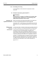
Operation SDC / DHC 4.1.2.7 ¤ "System information" button Calls up system information, such as temperatures and counter data. The information on the outside temperature appears first after the ¤ button is pressed. Turning the input button î causes the system temperatures and the counter and consumption states and operating states of the connected system components to appear. Pressing the input button î causes the respective setpoint values to appear.
SDC / DHC Operation Operating overview Press Turn input button to the left button Average/current outside temperature value Turn input button to the right Program/operating mode direct heating circuit/pump status Outside temperature min. to max.
Operation SDC / DHC Setting time for automatic return If the ¤ button is pressed and held for approx. 3 s, the INFO TIME parameter appears. With this parameter, the time it takes for automatic return to the basic display can be specified. Setting range Factory setting OFF No return. The last selected information display continuously remains in the basic display until the next change. 1 ... 10 min Automatic return from the information level after the specified time (in 0.5 minute increments).
SDC / DHC Operation The last value to which the control device adjusted the heat generator temperature appears as a recommendation. Cancellation Press button or operating mode. button, to return to the last selected Pos: 24 /156-Honeywell/Bedienung/Emmissionsmessung @ 1\m od_1207644670916_6.doc @ 9495 4.1.2.8.2 Emission measurement (not with district heating controllers) ATTENTION Emission measurements may only be carried out by the chimney sweep.
Operation SDC / DHC 4.1.2.9 Heating curve Determines the heating curve for the heating circuits. C The heating curve describes the relationship of the flow temperature change to the outside temperature change. With a larger heating surface, such as with floor heaters, the heating curve has a less extreme slope than with a smaller heating surface (e.g. radiators). The set value refers to the lowest outside temperature used for heat demand calculation.
SDC / DHC Operation Factory setting Direct heating circuit (HC) = 1,5 Mixed heating circuit 1 (MC-1) = 1 Mixed heating circuit 2 (MC-2) = 1 x y a x Boiler / flow temperature [°C] y Outside temperature [°C] a Troom [°C] Pos: 26 /156-Honeywell/Bedienung/Menue_Auswahlebene @ 1\m od_1207644710588_6.doc @ 9510 4.2 Menu-selection level The control device contains a menu-selection level that is structured differently, depending on the respective device version.
Operation SDC / DHC The menu functions are described in the following: System parameter Hot water Direct heating circuit Mixed heating circuit 1 Mixed heating circuit 2 Configuration Time - Date Configuration Parameter Programming 01 Time Language selection Nighttime hot water Heating curve Heating curve Heating curve 02 Year Time program Legionellaprotection day Reduced Reduced Reduced 03 Day Month Operating mode – Heating system Heating system Heating system 04 Change S
SDC / DHC Operation 4.2.1 "Time - Date" menu The following current calendar values can be specified in this menu: NOTE • Time • Year • Day - Month • Time change mode (summer / winter time) All listed daytime values are set at the factory and generally do not need to be updated. An internal, pre-programmed calendar ensures automatic time change on the annually recurring summer / winter time switchover dates. If necessary, the automatic time change can be deactivated.
Operation SDC / DHC 4.2.2 "Timeprograms" menu Individualised switching time programs for heating and hot-water operation can be created in this menu. Here, the factory-set default programs P1 (and, if enabled, P2 and P3 as well) of each heating circuit and the hot-water circuit are overwritten by individualised switching times and temperature specifications.
SDC / DHC Operation 4.2.2.1 Selection of the control circuit After accessing the "Timeprograms" menu, the desired control circuits can be selected with the input button î in the following sequence: • Direct heating circuit (HC) • Mixed heating circuit 1 (MC-1) • Mixed heating circuit 2 (MC-2) • Hot-water circuit (DHW) ► Press input button î to access the selected circuit. Pos: 30 /156-Honeywell/Bedienung/Auswahl_des_Programms @ 1\m od_1207644895088_6.doc @ 9570 4.2.2.
Operation SDC / DHC 4.2.2.4 Programming switching times and cycle temperatures Pos: 33 /156-Honeywell/Bedienung/Einschaltzeit @ 1\m od_1207645164353_6.doc @ 9615 4.2.2.4.1 Switch-on time The switch-on time is the start of heating or, with enabled switchon optimisation, the start of assignment. After selecting the day of the week and the corresponding cycle, the respective switch-on time appears flashing and can be set with the input button î.
SDC / DHC Operation NOTE The switch-off time cannot be set higher than the switch-on time of a subsequent cycle. If the switch-on time is changed, the corresponding time bar display is adjusted to the right-hand side. If the switch-off time is made equal to the switch-on time, the corresponding cycle is deleted. A subsequent cycle is automatically shifted to the position of the deleted cycle upon acceptance.
Operation SDC / DHC Switching time programming (programs P2 and P3 disabled) Upon accessing the menu-selection level, the "Timeprograms" menu always appears first. Enabling of programs P2 and P3 in the "System Parameters" menu (see 4.2 Menu-selection level, pg. 31).
SDC / DHC Operation Default switching time program (P1) for heating and hot water Uniform, continuous heating and hot-water operation on all days of the week Default program P1 Heating circuit Day Heating operation from to Heat generator heating circuit Mo to Su 6:00 22:00 Hot-water circuit Mo to Su 5:00 22:00 Mixed heating circuit 1 / 2 Mo to Su 6:00 22:00 Pos: 37 /156-Honeywell/Bedienung/Schaltzeitenprogramm ierung_freigeschaltet @ 1\m od_1207645530166_6.
Operation SDC / DHC Switching time programming (program P2 and P3 enabled) Upon accessing the menu-selection level, the "Timeprograms" menu always appears first. Enabling of programs P2 and P3 in the "System Parameters" menu (see 4.2 Menu-selection level, pg. 31).
SDC / DHC Operation Default program P1 Heating circuit Day Heating operation from to Mo to Su 6:00 22:00 Hot-water circuit Mo to Su 5:00 22:00 Mixed heating circuit 1 / 2 Mo to Su 6:00 22:00 Heat generator heating circuit Default program P2 Heating circuit Boiler heating circuit Hot-water circuit Mixed heating circuit 1 / 2 Day Heating operation from to from to Mo to Th 6:00 8:00 16:00 22:00 13:00 22:00 Fr 6:00 8:00 Sa to Su 6:00 22:00 Mo to Th 5:00 8:00 15:30 22:
Operation SDC / DHC 4.2.2.4.3.1 Copying switching time programs (days) Block programming enables the switching times and cycle temperatures of any day of the week to be copied 1 – To any days within the week (Mo, Tu, We, ..., Su) 2 – To all weekdays (Mo to Fr) 3 – To the weekend (Sa to Su) 4 – To the entire week (Mo to Su) Calling up the copy function (days) See flowcharts on pg. 44 Source day ► Press input button î to confirm the copy function.
SDC / DHC Operation Pos: 39 /156-Honeywell/Bedienung/Kopieren_von_Schaltzeitenprogrammen_Heizkreise @ 1\mod_1207645787619_6.doc @ 9705 4.2.2.4.3.2 Copying switching time programs (heating circuits) Block programming also enables the copying of all switching times and temperature specifications of a heating circuit to another heating circuit. Calling up the copy function (heating circuits) See flowcharts on pg. 44 Source circuit ► Press input button î to confirm the copy function.
Operation SDC / DHC Block programming The copy function enables a source day to be copied to any target days or to all days of the week (week programming). All cycles of the source day are copied. Individual heating cycles cannot be copied.
SDC / DHC Operation Copy day Select source day: Example: Monday Copy from Mo Select first target day: Example: Tuesday Copy to Mo Tu Copy day OK Mo ... Su Source day 1 target day or 1-7 (Mo ... Su) or 1-5 (Mo ... Fr) or 6-7 (Sa ...
Operation SDC / DHC Pos: 41 /156-Honeywell/Bedienung/Kopieren_von_Heizkreisen @ 1\m od_1207645944978_6.doc @ 9735 Copying heating circuits NOTE Select copy function: HC Heating circuits cannot be copied to hot-water circuits since they have different cycle temperatures: If a heating circuit is selected as the source circuit, the hot-water circuit can no longer be called up as the target circuit. The hot-water circuit as the source circuit is also the target circuit.
SDC / DHC Operation HC Direct heating circuit MC-1 Mixed heating circuit 1 MC-2 Mixed heating circuit 2 DHW Hot-water heating circuit 1) Program selection for source and target circuits are skipped if programs P2 and P3 are disabled in the "System Parameter" menu. Pos: 42 /156-Honeywell/Bedienung/Rueckladen_von_Standardprogramm en @ 1\m od_1207646077806_6.doc @ 9750 4.2.2.4.4 Reloading default programs See flowchart on pg.
Operation SDC / DHC ATTENTION With the setting value ALL, all heating circuits and the hotwater circuit are overwritten with their default switching times with regard to the selected program. When overwriting occurs, individually created switching time programs are permanently lost and must be recreated from scratch. Pressing the display.
SDC / DHC Operation Reloading default programs Switching time programs P2 and P3 disabled EN2H-0220GE51 R0308 HC Direct heating circuit MC-1 Mixed heating circuit 1 MC-2 Mixed heating circuit 2 DHW Hot-water heating circuit 49
Operation SDC / DHC Reloading default programs Switching time programs P2 and P3 enabled DHW HC Direct heating circuit MC-1 Mixed heating circuit 1 MC-2 Mixed heating circuit 2 DHW Hot-water heating circuit Pos: 43 /156-Honeywell/Bedienung/Menue_System parameter @ 1\m od_1207646151510_6.
SDC / DHC Operation 4.2.3 "System Parameters" menu The system parameters refer to general limiting parameters and specification values within the heating system. Access Returning See 4.2 Menu-selection level, pg. 31 Returning to the basic display takes place by pressing the button or automatically after the set information time (see 4.1.2.7 "System information" button, pg. 26). Pos: 44 /156-Honeywell/Bedienung/Sprachwahl @ 1\mod_1207646189369_6.doc @ 9780 4.2.3.
Operation SDC / DHC 4.2.3.2 Time program This parameter specifies enabling of the switching time programs for program selection and for individualised switching time programming. In the state of delivery, only one switching time program is enabled. This achieves simplification of operation with a large portion of applications for which only one switching time program is used.
SDC / DHC Operation 4.2.3.3.1 Setting Individualised daytime room temperature for each heating circuit ► Press ¥ button. ► Select desired heating circuit (HC, MC-1 or MC-2) by turning C the input button î. ► Confirm selected circuit by pressing the input button î. ► Set flashing room temperature specification to the desired value by turning the input button î. ► Confirm set value by pressing the ¥ button. Alternative: Automatic acceptance of the value after the set information time (see 4.1.2.
Operation SDC / DHC 4.2.3.3.3 Individualised operating mode for each heating circuit Each heating circuit can be assigned an individualised operating mode. Setting ► Press button. ► Select desired heating circuit (HC, MC-1 or MC-2) by turning C the input button î. ► Confirm selected circuit by pressing the input button î. ► Select flashing operating mode by turning the input button î. ► Confirm set operating mode by pressing the button or the input button î.
SDC / DHC Operation Undoing deactivation Deactivation is undone when the averaged and current outside temperature exceeds the set value by 1 K. The summer deactivation function is undone: NOTE • In case of an outside sensor defect • In case frost protection is active During deactivation phases (standby mode, manual summer operation, summer deactivation) lasting longer than 24 hours all pumps are switched on for approx.
Operation SDC / DHC If a reset is carried out, the RESET OK confirmation appears briefly. Verification is then started with a call-up of the first parameter in the respective menu once again. After the parameter values are reset, a return to the first parameter in the "System Parameter" menu occurs. Pos: 52 /156-Honeywell/Bedienung/Menue_Warmwasser @ 1\m od_1207647138228_6.doc @ 9930 4.2.
SDC / DHC Operation NOTE If a hot-water thermostat (see 05 parameter = transducer for hotwater circuit) is used to detect the hot-water temperature, these parameters are skipped. Pos: 55 /156-Honeywell/Bedienung/Menues_Direkheizkreis_Mischheizkreis @ 1\m od_1207647253025_6.doc @ 9975 4.2.5 "Direct Heating Circuit" / "Mixed Heating Circuit 1" / "Mixed Heating Circuit 2" menu These menus contain all parameters required to program the heating circuit, except the switch time programs. Max.
Operation SDC / DHC ECO (switch-off operation) During reduced operation, the direct heating circuit is switched off completely with outside temperatures above the set frostprotection limit. The maximum heat generator temperature is not functional. The heating circuit pump is switched off after a delay to avoid safety deactivation by reheating the heat generator (pump follow-up).
SDC / DHC Operation Factory setting Setting range 1,3 (radiator systems) 1,1 (floor heating) with mixed heating circuits 1 ... 10 Pos: 58 /156-Honeywell/Bedienung/Stoerm eldungen @ 1\mod_1207647364681_6.doc @ 10020 4.3 Error messages ATTENTION Inform the heating technician whenever any fault messages are output. The control device contains substantial error-notification logic. The error messages appear in continuous alteration with the basic display.
Log SDC / DHC 5 Log Weekly switching program Object: Mon (1) Set by: On: Cont. circuit Time Setpoint Opt. Tue (2) Cont. circuit Time Setpoint Opt. Wed (3) Cont. circuit Time Setpoint Opt. Thu (4) Cont. circuit Time Setpoint Opt. Fri (5) Cont. circuit Time Setpoint Opt. Sat (6) Cont. circuit Time Setpoint Opt. Sun (7) Cont. circuit Time Setpoint Opt.
SDC / DHC EN2H-0220GE51 R0308 Log 61
Log 62 SDC / DHC EN2H-0220GE51 R0308
Manufactured for and on behalf of the Environmental and Combustion Controls Division of Honeywell Technologies Sàrl, Ecublens, Route du Bois 37, Switzerland by its Authorized Representative: Automation and Control Solutions Honeywell House Arlington Business Park Bracknell, Berks, RG12 1EB Phone (44) 1344 656000 Fax (44) 1344 656644 http://honeywell.com/uk Printed in Germany All rights reserved. Subject to change without notice. EN2H-0220GE51 R0308 Art.