Airport Systems Installation and Operation Guide for High Intensity Obstruction Lighting System Model SG-60 Manual Number EPM-00000019-001 Honeywell Airport Systems 2162 Union Place Simi Valley, CA 93065 Phone (805) 581-5591 Fax (805) 581-5032 www.oblighting.com Copyright 2002 Honeywell Inc.
Airport Systems HISTORY OF REVISIONS Rev. A Comment First Release (New Boards) ECO# 3637 Approved S. Hammond Date 8/30/2002 NOTICE The integrity and reliability of Honeywell airport lighting systems are dependent on the use of Honeywell parts and components. To ensure the optimum performance and reliability of your Honeywell system, it is strongly advised that only components and modules provided by Honeywell be used.
Airport Systems DISCLAIMERS This manual could contain technical inaccuracies or typographical errors. Honeywell reserves the right to revise this manual from time to time of the contents thereof without obligation of Honeywell to notify any person of such revision or change. Details and values given in this manual are average values and have been compiled with care.
Airport Systems TABLE OF CONTENTS SAFETY INFORMATION ............................................................................................... V SECTION 1. GENERAL INFORMATION .....................................................................1-1 1.1 SCOPE ......................................................................................................................................1-1 1.2 GENERAL DESCRIPTION ....................................................................................
Airport Systems 3.3.4 Communications Circuitry ..............................................................................................3-10 SECTION 4. TROUBLESHOOTING ............................................................................4-1 SECTION 5. MAINTENANCE ......................................................................................5-1 5.1 SGC-60 MASTER CONTROLLER ..................................................................................................
Airport Systems SAFETY INFORMATION This section contains general safety instructions for using your Honeywell equipment. Task and equipment-specific Warnings are included in other sections of this manual where appropriate. Read all Warnings and follow all instructions carefully. Failure to do so may result in personal injury, death, or property damage. To use this equipment safely, refer to the following: 1.
Airport Systems QUALIFIED PERSONNEL The term “qualified personnel” is defined here as individuals who thoroughly understand the equipment and its safe operation, maintenance, and repair. Qualified personnel are physically capable of performing the required tasks, familiar with all relevant safety rules and regulations and have been trained to safely install, operate, maintain, and repair the equipment.
Airport Systems WARNING! KEEP AWAY FROM LIVE CIRCUITS. OPERATION AND MAINTENANCE PERSONNEL MUST OBSERVE ALL SAFETY REGULATIONS AT ALL TIMES. DO NOT CHANGE PLUG-IN COMPONENTS OR MAKE ADJUSTMENTS INSIDE EQUIPMENT WITH THE HIGH VOLTAGE SUPPLY ON. UNDER CERTAIN CONDITIONS, THERE IS A POTENTIAL FOR SERIOUS INJURY FROM CIRCUITS WITH POWER CONTROLS IN THE OFF POSITION. THIS IS DUE TO CHARGES RETAINED BY THE CAPACITORS.
Airport Systems SECTION 1. GENERAL INFORMATION 1.1 Scope This manual provides information about the installation, operation, and maintenance of the StrobeGuard, Model SG-60, High Intensity Obstruction Lighting System manufactured by Honeywell. 1.2 General Description The StrobeGuard system is a high intensity flashing white obstruction lighting system with a xenon flashtube as the light source. It designed for use as a high intensity aviation obstruction warning system.
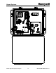
Airport Systems Figure 1-1: Model SGC-60 Master Controller SG-60 High Intensity Strobe System 1-2 Manual EPM-00000019 Rev A
Airport Systems Figure 1-2: Model SGF-60 Flashhead SG-60 High Intensity Strobe System 1-3 Manual EPM-00000019 Rev A
Airport Systems 1.3 Safety Precautions The following general safety precautions must be observed during all phases of operation, service, and repair of this equipment. Failure to comply with these precautions or with specific warnings elsewhere in this manual violates safety standards of design, manufacture, and intended use of this equipment. Honeywell assumes no liability for the customer’s failure to comply with these requirements, as listed below. 1.
Airport Systems WARNING! This system uses lethal voltages in the Flashhead. Unless absolutely necessary, do not attempt to service or adjust the equipment with AC line power applied. Safety interlock switches are provided in the Flashhead enclosure to interrupt main AC power to the power supply. These interlock switches are activated when the Flashhead door is opened in a conventional manner. No interlock is provided when other means of access are used.
Airport Systems 1.4 Specifications Light Output: Day Intensity..............................................270,000 ±25% effective candelas, single flash Twilight Intensity..........................................20,000 ±25% effective candelas, single flash Night Intensity......................................... 2,000 ±25% effective candelas, burst of flashes Beam Pattern...............................................................120º horizontally, 3 º min. vertically max.
Airport Systems Flashhead Fail......................................... Relay K1 de-energized and LED DS29 Off Photocell Fail .......................................... Relay K2 de-energized and LED DS30 Off Power Fail................................................ Relay K3 de-energized and LED DS31 Off Night Mode Operation ............................. Relay K4 de-energized and LED DS32 Off White Night Backup (Dual Systems) ...........
Airport Systems SECTION 2. INSTALLATION & POWER UP WARNING! Modifications to the Power Supply are required for certain applications. Remove input power at circuit breakers and discharge capacitors with an approved grounding rod before attempting any necessary modifications. 2.1 Unpacking Carefully unpack each item and remove any internal packing material from the master controller, and the flashhead/power supply.
Airport Systems 2.2.1.
Airport Systems • SW2 – (Figure 2-10, Item 2, Page 2-25) This switch is used to set for Catenary operation (suspended cable warning lights) and for Dual systems (Red lights at night, and white strobes during the day). § SW2-1 – Set to ON (up) for Catenary system. § SW2-2 – Set to ON (up) for Dual system. § SW2-3 – Set to OFF (down). Reserved for future use. • SW3 – (Figure 2-10, Item 8, Page 2-25) This switch is used to set the termination resistor for the communications line.
Airport Systems 2.2.2.1 Power Configuration The Flashhead(s) are factory set for the correct AC input line voltage. However, the user shall verify that the AC line voltage selector block (located on the transformer board on top of transformer T1, Figure 1-2, Page 1-3) is labeled with the correct AC line voltage used at the site. For example, voltage selector block part number 77-3319 is labeled for 120VAC.
Airport Systems • SW3 – (Figure 2-11, Item 3, Page 2-26) Used to specify the ID number for the Flashhead. Each Flashhead must be set with a unique ID number as indicated on the installation drawings. There is a diagram next to the switch showing the values for the switch. The ID number is the total of the values of the switches set to OFF (negative binary). For example, to set ID #10, set SW3-2 (value 2) OFF (down) and SW3-4 (value 8) OFF (down) for a total of 10 (2+8).
Airport Systems 7. Refer to Figure 2-1 below. Dress the electrode wires away from the sides of the reflector. 8. Close and fasten the Flashhead cover. Figure 2-1: Flashtube Installation 2.3 2.3.1 Installation SGC-60 Master Controller The Master Controller is connected to Flashheads via the data communications cable provided by Honeywell. The length of this cable (up to 2500 feet) determines how far the Master Controller can be mounted from the Flashheads.
Airport Systems Typically, the Flashhead is mounted to a bracket, which is then attached to the structure. Honeywell can supply brackets for most types of installations. A detailed drawing for mounting the Flashhead is shown in Figure 2-3, Page 2-10. 2.3.2.1 Setting the Flashhead Elevation Flashheads must be mounted at the proper vertical angle to assure proper light output. Depending on the elevation of the light level, the Flashhead may need to be adjusted to reduce the amount of ground scatter.
Airport Systems 2.3.4 Cables and Junction Boxes The cables shall be properly supported and terminated in the junction boxes per the detailed description provided in section 2.4, page 2-11 of this document. Additional information regarding cables and junction box installation can be found on the drawing set for the lighting system. Particular attention should be paid to assure that the data cable shields are isolated from the junction box housings.
Airport Systems Figure 2-2: Master Controller Mounting Dimensions SG-60 High Intensity Strobe System 2-9 Manual EPM-00000019 Rev A
Airport Systems Figure 2-3: Flashhead Outline and Mounting Dimensions SG-60 High Intensity Strobe System 2-10 Manual EPM-00000019 Rev A
Airport Systems 2.4 Installation Wiring Follow the procedure below to perform the installation wiring. Note that the wiring of the Alarm Relay outputs is customer and site specific and is therefore not specified in this manual.
Airport Systems 2.4.1 Master Controller to Photocell Wiring The photocell is supplied with a length of wire attached. If a longer wire is needed, this should be accomplished using a junction box. Make the interconnect between the external Photocell and the Master Controller TB2 per Figure 2-5, Page 2-11, as follows. Black wire White wire Red wire 2.4.
Airport Systems 2.4.4 Master Controller Wiring For Dual Systems If your installation is a Dual (Red/White) system, you must make additional connections to coordinate between the High Intensity Strobe System and the Red Light System. See the sections below for wiring details. For configuration switch settings for a Dual system, see 2.2.1.3 on Page 2-2. 2.4.4.1 Controlling the Red Light System The Master Controller uses Relay K4 to control the Red Light System.
Airport Systems If your red light system has a Honeywell 9LCA Series Red Light Controller, locate the Alarm terminals and Flasher Bypass terminals corresponding to the top beacon, and make the following connections: Master Controller TB6-1 -----------------to ----------------------9LCA Flasher Bypass C1 9LCA Flasher Bypass NC1 -------------to ---------------------------- 9LCA Alarm Card C1 Master Controller TB6-2 -----------------to --------------------------9LCA Alarm Card NC1 Note: Usually the top beacon
Airport Systems Figure 2-5: Flex Conduit Typical Installation Layout 2.4.6.1 Procedures for installation of conduit and tower wiring 1. All conduit, junction boxes, mounting hardware, fixtures, etc. provided for installation of the electrical system (i.e. lighting or equipment power distribution) should be inventoried and checked against the appropriate bills of materials.
Airport Systems the junction box ports. Do not begin to run wire through a junction box port before a chase nipple or grommet is in place. 5. Before running the wire into a box insure the wire insulation will be protected from any sharp edges on the junction boxes. Pieces of carpet, wide copper braid, etc. can be fastened in place over sharp edges to protect wire insulation. 6.
Airport Systems (f) (g) and the connection should be at the top end of the junction box. Wiring from ports in the sides of junction boxes should also be made such that the wire nuts are at the top of the junction box with the wire nut openings pointing downward, (see Figure 2-6, Page 2-19) for proper moisture protection. Move down to the next intermediate (strain relief) junction box and pull enough of the wiring into the box to provide for the proper installation of the strain relief mechanism.
Airport Systems 2.4.7 Junction Box Details This section will detail the proper wire interconnection details for the input voltage and data cable to the flashhead pigtail cable. These connections are very important to the proper operation of the lighting system. The flashhead pigtail contains all the wires required for proper interconnection between the conduit wiring and flashhead. Additional reference materials can be found on the High Intensity Lighting system drawing set.
Airport Systems Figure 2-6: Junction Box Wiring Details SG-60 High Intensity Strobe System 2-19 Manual EPM-00000019 Rev A
Airport Systems Figure 2-7: Flex Conduit Installation Detail SG-60 High Intensity Strobe System 2-20 Manual EPM-00000019 Rev A
Airport Systems The flex conduit will need to be properly mounted to the horizontal and vertical struts by way of the supplied 20-inch cable ties. These cable ties should be placed at a minimum of 3 feet apart for proper bonding to the tower structure. The distance between the cable ties may need to be reduced if the installer sees that the 3-foot distance will not allow for proper bonding and securing to the tower.
Airport Systems Item 6 is a shield drain wire that will not be used for interconnection. This wire should be cut off flush from the cable when the outer jacket is stripped back for interconnection of the system. The following section is a guideline to a proper installation of the WC000001 cable. Please follow this guideline to ensure a proper installation and interconnection in the junction box. 1. Strip back at least 16” of the outer jacket of the WC000001 cable.
Airport Systems 9. The power wires should be spliced together using split bolt connectors. The data wires should be spliced together using Scotch® Twist Lock connectors. After splicing, ensure all wires are secure by pulling on each wire. Wrap each connection with at least 6 wraps of Scotch 33+ tape or equivalent for moisture protection. All connection ends should be located in the upper corners of the junction box with all closed end of the connector pointing up. See Figure 2-6, Page 2-19 for reference.
Airport Systems ** It is extremely important to connect all Data cable inner shields together, but isolate them from all other shields and grounds ** Figure 2-10: Flashhead Cable SG-60 High Intensity Strobe System 2-24 Manual EPM-00000019 Rev A
Airport Systems Figure 2-10: Master Controller Circuit Board SG-60 High Intensity Strobe System 2-25 Manual EPM-00000019 Rev A
Airport Systems Figure 2-11: Flashhead Digital Control Board SG-60 High Intensity Strobe System 2-26 Manual EPM-00000019 Rev A
Airport Systems 2.5 Final Installation Check Before applying power to the equipment, perform the procedures in Sections 2.5.1 2.5.4. If any test does not pass, please consult SECTION 4. TROUBLESHOOTING in this manual or call Honeywell Technical Support at (805) 581-5591. 2.5.1 Preliminary 1. Verify that all AC input power circuit breakers are turned off. 2. Check that all printed circuit boards are properly seated in their sockets, and retaining brackets are securely fastened.. 3.
Airport Systems 6. Verify open circuit between TB5-S and TB5-A (both on Data Cable) 7. Verify open circuit between TB5-S and TB5-B (both on Data Cable). 8. In one of the top-most Flashheads, install a jumper (or alligator clip) between TB1-5 and TB1-6. 9. Verify short circuit between (<20 ohms) TB5-S and TB5-B (both on Data Cable). 10. Remove the jumper between TB1-5 and TB1-6. 11. Verify open circuit between TB5-S and TB5-B (both on Data Cable) 12.
Airport Systems § § § § 2.6.2 DS32 - 33 – (Figure 2-10, Item 5, Page 2-25) The indications on these lights are dependent on the setting for external red light system on SW2. If SW2-2 is set for an EXTERNAL RED system (ON), then • DS32 – ON indicates there has been a red light system alarm sometime during the night and the red light system is off, but will reset the next day.
Airport Systems 7. Verify that the LED test sequence has started. The test sequence will exercise every LED and relay (e.g. it will quickly sweep through the Flashhead Status LEDs in red and green mode). After the test sequence completes, the Flashhead status LEDs for the selected number of Flashheads shall be lit red then change to green as the Flashheads report (DS1 - DS24, Figure 2-10 Item 4, Page 2-25). 8.
Airport Systems 6. If you have a Dual (Red/White) System, the Red Lights should be OFF. 7. If you have a Catenary System, Verify Catenary flash timing. 2.6.4.2 (a) All Flashhead on Middle Level should flash together. (b) All Flashheads on Top Level should flash together (c) All Flashheads on Bottom Level should flash together. (d) Middle Level Flashheads should flash first.
Airport Systems 6. 7. If you have a Dual (Red/White) System: Verify normal red night mode operation. (a) Verify that all Flashheads are OFF (b) Verify that all Red Lights are ON and flashing properly, and the Red Light Controller does not indicate any alarms in the top-most Red Beacons. (c) Verify that LED DS36 (EXT RED READY) is lit green (See Item 10, Figure 2-10, Page 2-25). If you have a Dual (Red/White) System: Perform the following steps to check white night backup operation.
Airport Systems 2.6.5 Verify Photocell Operation Connected to Controller 1. Verify proper mounting and orientation of photocell. Photocell shall face toward the polar sky (e.g., North in the northern hemisphere), not toward the sun. 2. Set LOCAL / REMOTE switch to REMOTE. 3. Verify that the correct Mode status LED (DS25 - DS27 Figure 2-10, Item 3, Page 2-25) is lit red according to the ambient light conditions (during normal daylight, DS25 shall be lit red). 4.
Airport Systems for normal operation. If any test did not pass, please consult SECTION 4. TROUBLESHOOTING in this manual or call Honeywell Technical Support at (805) 5815591.
Airport Systems SECTION 3. PRINCIPLES OF OPERATION 3.1 Overall Description The SG-60 High Intensity Obstruction Lighting System meets the requirements of the FAA Advisory Circular 150/5345-43E. Depending on system configuration, the Flashheads are either type L-856 (simultaneous flashing, 40 flashes per minute (FPM)) or type L-857 (catenary flash pattern 60 FPM).
Airport Systems energy storage capacitors discharge rapidly through the flashtube. The high discharge current briefly heats the xenon gas to great temperatures, producing a bright flash. The short-circuit output current of the T1 transformer is limited to less than the flashtube's shut-off current. Once the capacitors discharge below a certain level, the current flowing through the tube cannot keep the xenon gas ionized, and the flashtube becomes a non-conductor and shuts off (self-extinguishes).
Airport Systems WARNING! HIGH VOLTAGE is on the energy storage capacitors C1, C2, C3A and C3B when the High Voltage Indicator DS1 indicator is lit! (DS1 is the neon lamp located on the High Voltage & Trigger board - do not confuse the High Voltage Indicator DS1, with the PWR ON lamp DS1.) It is possible to have high voltage on the energy storage capacitors even if all AC power has been removed from the system, even though the system is designed to drain the energy storage capacitors when power is removed.
Airport Systems The Digital Board functions are discussed in more detail below. 3.2.2.1 Power Supplies The Digital board rectifies (DB1) and filters (C4) the 24VAC output of the Flashhead T2 transformer, and uses the resulting unregulated voltage to power the K1, K2, and K3 relays. The K3 relay coil is wired directly to this supply. K3 will be energized whenever power is supplied to the digital board. Power to the K1 and K2 relay coils is controlled by the micro-controller.
Airport Systems position is shown on the board silkscreen. Note that ON means zero, and that OFF means the indicated value (negative binary). The Digital Board will only transmit a reply when its number is specified by the Master Controller. The Digital Board monitors its transmission quality by reading the transmission as it sends it. The green LED DS3 indicates the current communications status. It is updated after every flash.
Airport Systems 3.2.2.4 Flash Control To fire the flashtube, the Digital Board pulls down the trigger request line (P2-17) for about 500uS. This signals the Trigger/High-Voltage Card to trigger the flashtube. The Digital Board will issue its trigger request on a T2 zero-crossing. (Normally, the first zero-crossing it detects after receiving a flash request from the Master Controller.) In Day and Twilight modes, the Digital Board will issue a single trigger request.
Airport Systems 3.2.3.1 High Voltage Rectification This section of the Trigger/High-Voltage Board provides the DC to charge the energy storage capacitors that power the flashtube. The high voltage AC from the ferro-resonant power transformer T1 pins T1-7 and T1-8 is output to the Trigger/High-Voltage board through the Flashhead motherboard pins E5 and E6, respectively. The high-power diode bridge DB1 rectifies the incoming 2000Vp-p voltage to pulsed 2000VDC.
Airport Systems 3.3 3.3.1 SGC-60 Master Controller Power Supply The Master Controller input power is connected to PB1, which then feeds transformer T1 (under the switch panel). The Master Controller can accept a number of input voltages, depending on the primary tap connections to T1, and will operate at 50 or 60 Hz. The T1 transformer output provides 12VAC to the Master Controller circuit board PCB1 (T1-17 and T1-18 connecting to PCB1 TB1-1 and TB1-2).
Airport Systems The Master Controller gives previously good Flashheads four chances to reply (addressing that Flashhead repeatedly), before marking them bad. Previously bad Flashheads are given one chance to reply OK before moving on to the next Flashhead. The Master Controller checks the status of each Flashhead in order of increasing flashhead number, cycling repeatedly through the total number of selected Flashheads. You can set the number of Flashheads monitored using DIP Switch SW1.
Airport Systems during the daytime. In this case, the Master Controller will briefly try the Red Lights each night until the top beacon is repaired. Troubleshooting Tip: To check system communications independent of most Flashhead failures, place a jumper across TB6-1 and TB6-2, set SW2-2 On, and select Local Night Mode from the switch panel. Because an Off Mode "flash" cannot fail, all the Flashheads will reply OK if they can.
Airport Systems Figure 3-1: Master Controller Board Schematic SG-60 High Intensity Strobe System 3-11 Manual EPM-00000019 Rev A
Airport Systems Figure 3-2: SGF-60 Flashhead System Schematic SG-60 High Intensity Strobe System 3-12 Manual EPM-00000019 Rev A
Airport Systems Figure 3-3: SGF-60 Digital Board Schematic SG-60 High Intensity Strobe System 3-13 Manual EPM-00000019 Rev A
Airport Systems Figure 3-4: SGF-60 Trigger/High-Voltage Board Schematic SG-60 High Intensity Strobe System 3-14 Manual EPM-00000019 Rev A
Airport Systems SECTION 4. TROUBLESHOOTING Refer to the troubleshooting flowcharts. Replace components in the order stated, and keep track of those replaced. The following troubleshooting procedures presume that all fuses, interlocks, and controls are functioning properly. Note that the troubleshooting flowcharts are intended to be used as a general guide, and do not cover every possible mode of failure. WARNING! 1. Always turn off power when changing any component or printed circuit board. 2.
Airport Systems The charts assume that that you have already eliminated these as possible causes for the observed problem. The charts may instruct you to make temporary changes for testing (such as select operating modes manually, or installing a jumper). These temporary measures are marked with rectangles with rounded corners. Always return the systems to their normal state after completing your troubleshooting. To reduce chart complexity, the charts not specify the individual actions necessary.
Airport Systems All Flashheads stuck in Day Mode Are any LEDs on Master Controller lit? No Replace MC Fuse F1. Yes Does MC show Green FH Status LEDs? Does MC show Green PC OK LED (DS28?) Yes Troubleshoot Flashheads Individually. Yes Check Photocell Wiring. If wiring OK, replace Photocell. No No Is Master Controller COM OK LED lit? (DS34) No No Unplug MC TB5 Is Master Controller COM OK LED lit? (DS34) Yes Check for shorts between communication cable and power wiring.
Airport Systems This test assumes that F1 and F2 have tested OK. Flashhead does not flash Is FH Flashtube broken? Yes Replace Flashtube. Microcontroller Failure. Replace Digital Board. No Is THVB DS1 High Voltage Indicator Lit? Yes Is DB DS1 red LED (+5V Indicator) lit? No Press DB SW1 pushbutton 1 sec and release. No Remove Power at Breakers. Discharge Capacitors. Is FH capacitor C1A, C1B, C2, C3, or C4 shorted out? Yes Power Supply Failure: Replace Digital Board.
Airport Systems Flashhead stuck in Day Mode Is DB DS3 green LED steady off? No Yes Are Comm wires correctly wired in FH 1 TB1? Will FH operate in other modes with manual selection? Check if problem is resolved after each step taken. 1. Replace Digital Board. 2. Check for loose connections to coil of FH K2 Relay 3. Replace FH K2 relay. No Check for loose mounting nuts on FH switch assembly. Make sure FH Remote/Local interlock is pressed when door latched. Yes No Correct wiring.
Airport Systems Red Lights don’t turn on at night. Is MC K4 wired to RLC Photo Input? No 1. Disconnect RLC Photocell. 2. Connect wiring from MC Red/Night relay K4 to RLC 1 Photocell Input. Yes Is MC TB6 wired to RLC Top Beacon Alarms? No Connect wiring from MC TB-6 to 2 Top Red Beacon alarms. Manually turn on Red Lights at RLC. Does MC Red Ready LED light up (DS36)? Yes Check wiring from MC Red/Night 1 relay K4 to RLC Photocell Input.
Airport Systems All Flashheads are flashing together, but not in catenary pattern. All Flashheads flash too slow (40 flashes per minute). No Does MC show Green FH Status LED for each working FH? Does MC show Green FH Status LED for each working FH? No Does MC show Green FH Status LED for that FH? No Yes Yes Set MC switch SW-2 to on. A Flashhead is out of sync with its catenary level.
Airport Systems SECTION 5. MAINTENANCE 5.1 SGC-60 Master Controller The Master Controller required no periodic maintenance. instructions for installing a new transformer 5.1.1 However, below are the Transformer Replacement SGC-60 Replacement Transformer see step 10 Figure 5-1: SGC-60 Replacement Transformer Transformer replacement instructions. 1. 2. 3. 4. 5. 6. 7. 8. 9. Open Controller unit and set power switch to off. Secure Controller input power at the circuit breaker.
Airport Systems 10. 11. 12. 13. 14. 15. 16. 5.2 Attach wires with the push on connectors to the following terminals. (a) White wire to the outer bottom right terminal (b) Black wire to the terminal that matches the Controller input voltage. (240v shown in Figure 5-1.) You will need to replace the terminal lugs on the other 2 white wires before attaching to the transformer. (a) Cut off wire terminal lugs as close to lug as possible (b) Strip insulation back and crimp on new push on connectors.
Airport Systems 5. Unpack the new flashtube. Do not touch the glass envelope - contamination from a fingerprint will degrade the reliability of the flashtube. 6. Holding the flashtube by its metal ends, center it in the reflector assembly and snap it into place. Make sure the red mark on the flashtube matches the red mark on the socket assembly. 7. Attach the faston connector at each end of the flashtube to each socket assembly. Make sure wires are not twisted - the metal to glass bond is fragile. 8.
Airport Systems SECTION 6. REPLACEMENT PARTS Description Part Number SGF-60 Flashhead Capacitor, 1µF, C1----------------------------------------------------- 77-4220 Capacitor, 3µF, C4----------------------------------------------------- 77-3311 Capacitor, 12.
Airport Systems SECTION 7.
Airport Systems Figure 7-1: SG-60 AOL Flashhead Mounting Dimensions SG-60 High Intensity Strobe System 7-2 Manual EPM-00000019 Rev A
Airport Systems Figure 7-2: SG-60 AOL Power Supply Mounting Dimensions SG-60 High Intensity Strobe System 7-3 Manual EPM-00000019 Rev A
Airport Systems Figure 7-3: SG-60 AOL Wiring Installation SG-60 High Intensity Strobe System 7-4 Manual EPM-00000019 Rev A
Airport Systems Figure 7-4: SG-60 AOL Flashhead Component Locations SG-60 High Intensity Strobe System 7-5 Manual EPM-00000019 Rev A
Airport Systems Figure 7-5: SG-60 AOL Power Supply Component Locations SG-60 High Intensity Strobe System 7-6 Manual EPM-00000019 Rev A
Airport Systems Figure 7-6: SG-60 AOL Schematic SG-60 High Intensity Strobe System 7-7 Manual EPM-00000019 Rev A