
Install Instructions


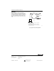


Table Of Contents

SP470A AND B PNEUMATIC SWITCHES
WARNING
The SP470 switch body is made of
polycarbonate plastic resin (Lexan) which can
be adversely affected by certain chemicals.
Avoid using strong alkaline, aromatic
hydrocarbon, and chlorinated hydrocarbon
solutions on the switch body. Cleaning
solvents and leak detection solutions should
consist of water, mineral acids and organic
acids.
INSTALLATION
Mounting
When mounting the SP470A on a panel, it is necessary
to drill a 5/8 in. (16 mm) hole through the panel at the
mounting location. Insert the threaded neck of the device
through the hole and align the scale plate with the notch
in the threads. See Fig. 4. Secure the scale plate with the
round nut. Align the set screw on the knob with the flat
surface on the shaft and secure it. The SP470A can also
be mounted in a standard electrical box using Assembly
316813A. See Fig. 5.
When using the SP470B for surface mounting, determine
the mounting location and hold the SP470B in place. See
Fig. 6. Mark the hole locations and drill. Fasten the
device to the location with bolts or screws (not provided).
2
1
3
S
P470A
SCALEPLATE
NUT
KNOB-ALIGN SET
SCREW WITH
FLAT ON SHAFT
DRILL A
5/8 IN.
(16MM)
HOLE
PANEL OR WALL
NOTE: PROVIDE A MINIMUM OF 2.9 IN. (73.6MM)
BETWEEN CENTERS OF ADJACENT SWITCHES
C7250-1
Fig. 4. SP470A flush mounting.
Fig. 5. SP470A installation using assembly 316813A.
SCREW-8-32X1/2"
RD HD(2)
SP470A
316813 MOUNTING
BRACKET
SCREW-6-32 X 1/4
PAN HEAD (4)
4 X 4X1-1/2 in.
(102 X 102 X 38mm)
ELECTRICAL BOX
ADAPTOR RING
(ANY DEPTH)
HEX
NUT
14004628-001
HEX NUT
316862 COVER
80268H
SCREW-
6-32X1/2"
FLT HD(2)
C7251-1
2
1
3
14004396-9001
PANEL BRACKET
SP470B
3-1/2
(89)
3-1/4
(83)
4-1/2
(114)
2-7/16
(62)
C7252
Fig. 6. SP470B surface mounting.
Piping
Fig. 7 shows adaptation piping. All connections are sharp
barb 5/32 in. (4 mm) O.D. polyethylene tubing. Carefully
push the air lines over the barb fittings. No clamp is
required. DO NOT attempt to remove the tubing from the
fittings.
CONNECT
1/4 IN.
(6 MM)
COPPER
SP470A1B
POST FOR
CONNECT
1/4 IN.
(6 MM)
PLASTIC
5/32 IN. (4 MM) O.D.
PLASTIC TUBING
5/32 IN. (4 MM)
O.D. PLASTIC
TUBING CUT
TO LENGTH
5/32 IN. X 1/4 IN.
(4 MM X 6 MM)
O.D. PLASTIC
CONNECTOR
(CCTI606B)
1/4 IN. (6 MM)
O.D. PLASTIC
TUBING CUT TO
LENGTH
1/4 IN. (4 MM) O.D.
PLASTIC/COPPER
ADAPTER
(CCTI633BT)
1/4 IN. (6 MM) O.D.
COPPER TUBING
C8135
Fig. 7. Adaptation piping.
95-7236EF 2