
Install Instructions


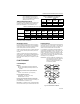
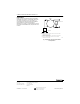
Table Of Contents

SP470A and B
Pneumatic Switches
INSTALLATION INSTRUCTIONS
the switch only, and the SP470B is the switch mounted in
DESCRIPTION
a panel. These switches are available in two- or
three-position models and can be panel or line mounted.
The SP470A and B Pneumatic Switches manually divert
air between various system components such as valve
Figs. 1, 2 and 3 show approximate dimensions in inches
and damper actuators and thermostats. The SP470A is
(millimeters).
Fig. 1. SP470A and B switch dimensions.
1-3/16
(30)
1-1/2
(38)
1
(25)
1-1/2
(38)
1-1/2
(38)
C8142
1-1/2
(38)
3/8 FLAT
(10)
1-1/8
(29)
13/16
(21)
19/32
(15)
3
(76)
1-3/16
(30)
1 3
2
3-1/2
(89)
1
(25)
4-1/2
(114)
C8143
1-9/16
(40)
(14003269-001)
(14003269-002)
C8285
"A"
.05(1.3)
Fig. 3. Scaleplate dimensions.
2-7/16
BEFORE INSTALLATION
(62)
3-1/4
(
83
)
The SP470A is normally mounted on a panel that can be
Fig. 2. SP470B switch dimensions.
up to 7/16 in. (11 mm) thick.
2-3/4
(70)
1 3
2
30°
2-3/4
(70)
DETAIL
"A"
DETAIL
3
-POSITION SCALEPLATE
2-POSITION SCALEPLAT
E
1 2
2-3/4
(70)
® U.S. Registered Trademark
Copyright © 2002 Honeywell • All Rights Reserved
95-7236EF