ST 3000 Smart Transmitter Release 300 and SFC Smart Field Communicator Model STS 103 Installation Guide 34-ST-33-39 2/05
Copyright, Notices, and Trademarks Printed in U.S.A. – © Copyright 2005 by Honeywell Inc. February 2005 While this information is presented in good faith and believed to be accurate, Honeywell disclaims the implied warranties of merchantability and fitness for a particular purpose and makes no express warranties except as may be stated in its written agreement with and for its customer. In no event is Honeywell liable to anyone for any indirect, special or consequential damages.
About This Publication This manual is intended as a handy guide for installing ST 3000® Release 300 Smart Transmitters. It provides data for checking out, mounting and wiring the transmitter as well as detailed wiring diagrams for reference. Much of this same information is also included in the ST 3000 Smart Transmitter Release 300 and SFC® Smart Field Communicator Model STS 103 User’s Manual 34-ST-25-14 which is the main reference document.
References Publication Title Publication Number ST 3000 Smart Transmitter Release 300 and SFC Smart Field Communicator Model STS 103 User’s Manual 34-ST-25-14 SCT 3000 Smartline Configuration Toolkit Start-Up and Installation Manual 34-ST-10-08 Smart Field Communicator Model STS103 Operating Guide 34-ST-11-14 Binder Title Binder Number For R400 and later: PM/APM Smartline Transmitter Integration Manual PM12-410 Implementation/ PM/APM Optional Devices TDC 2045 Symbol Definitions This CAUTION
Table of Contents REFERENCES .................................................................................................................. IV TECHNICAL ASSISTANCE............................................................................................. VIII SECTION 1 —GETTING STARTED ................................................................................... 1 1.1 CE Conformity (Europe) Notice.................................................................................................
Figures and Tables Figure 1 Figure 2 Figure 3 Figure 4 Figure 5 Figure 6 Figure 7 Figure 8 Figure 9 Figure 10 Figure 11 Figure 12 Figure 13 Figure 14 Figure 15 Figure A-1 Figure A-2 Typical Power Supply and SCT/SFC Connections to ST 3000. ............................................ 6 Location of Failsafe Direction Jumper on PWA. .................................................................. 14 Write Protect Jumper Location and Selections.................................................................
Acronyms AP ............................................................................................................................ Absolute Pressure APM ......................................................................................................... Advanced Process Manager AWG .................................................................................................................. American Wire Gauge DE ................................................................................
Technical Assistance If you encounter a problem with your ST 3000 Smart Transmitter, check to see how your transmitter is currently configured to verify that all selections are consistent with your application. If the problem persists, you can reach Honeywell’s Solution Support Center for technical support by telephone during normal business hours. An engineer will discuss your problem with you. Please have your complete model number, serial number, and software revision number on hand for reference.
IMPORTANT Before You Begin, Please Note Depending on your transmitter options, the transmitter may be equipped with either a 3-screw or 5-screw terminal block inside the electronics housing. This may affect how to connect the loop wiring and meter wiring to the transmitter. See Section 4.3 for the terminal block connections for each type terminal. Section 5 provides additional wiring diagrams showing alternate wiring methods.
x ST 3000 Release 300 Installation Guide 2/05
Section 1 —Getting Started 1.1 CE Conformity (Europe) Notice About conformity and special conditions This product is in conformity with the protection requirements of 89/336/EEC, the EMC Directive. Conformity of this product with any other “CE Mark” Directive(s) shall not be assumed. Deviation from the installation conditions specified in this manual, and the following special conditions, may invalidate this product’s conformity with the EMC Directive.
1.2 Preliminary Checks Checking ST 3000 shipment Along with this Installation Guide you should have received • the ST 3000 Smart Transmitter you ordered, and • an optional mounting bracket assembly, if applicable. Before you dispose of the shipping container, be sure you have removed all the contents and visually inspected the transmitter for signs of shipping damage. Report any such damage to the carrier. Contact us if there is a problem with the order or an item is missing.
1.2 Preliminary Checks, Series and model number data, continued ATTENTION Continued For a complete breakdown of the table selections in your model number, please refer to the appropriate Specification and Model Selection Guide that is provided as a separate document. Previous models of the ST 3000 transmitter with designations of Series 100, Series 100e, Series 600, and Series 900 have been supplied at various times since the ST 3000 was introduced in 1983.
1.2 Preliminary Checks, Communicating with the ST3000 Transmitter, continued Continued Using the SFC: If you ordered an SFC along with your transmitter, locate it and follow the instructions supplied with the SFC Model STS103 to prepare it for operation. Otherwise, be sure you have a fully charged SFC Model STS103 on hand to check the operation of your transmitter. NOTE: SFC model STS103 with software version 5.
Section 2 —Optional Bench Check 2.1 Connecting Power and SCT/SFC About the bench check The bench check is an optional procedure for checking your transmitter before you install it by: • Connecting a power source and an SFC (or a PC running SCT 3000 software) to the transmitter • Running a communication test with an SFC (or SCT 3000) • Checking the operation status and checking the configuration database Also, if your transmitter was not configured at the factory, you can do so during this procedure.
2.1 Connecting Power and SCT/SFC, Continued Do not try to remove the transmitter housing end-cap before loosening the end-cap lock on the transmitter housing. Table 1 Connecting Power Supply and SFC to ST 3000 CAUTION Step Action 1 Use a 1.5 mm allen wrench to loosen the end-cap lock on the terminal side of the transmitter housing.
2.2 Testing Communications Background Once you connect power and the SCT or SFC to the transmitter, you are ready to test communications with the transmitter. Procedure The procedure in Table 2 outlines the steps using an SFC for initiating communications with an ST 3000 transmitter without an assigned tag number. Table 2 Step Testing Communications with Transmitter.
2.2 Testing Communications, Continued Procedure, continued Table 2 Step 5 Testing Communications with Transmitter, Continued Press Key Read Display or Action T A G N O . S F C W O R K L I N D P Description I N G . . . T A G _ N O . OR D E – X M T R T A G _ N O . OR T A G N O 6 N O .
2.2 Testing Communications, Continued Procedure, continued Table 2 Step 7 Testing Communications with Transmitter, Continued Press Key ^ SHIFT DE READ A ID Read Display or Action D E – X M T R T A G S H I F T – T A G N O . S F C W O R K L 8 F/S DIR U STAT I N D P N O . I N G – . 3 3 % T A G _ N O . I N G . . W O R K L I N C H E C K = O K D P R E A D Y . Begins upload of configuration database from transmitter. Operation completion rate is shown in percent.
2.3 Verifying Configuration Data Procedure Use the procedure in Table 3 to display all the basic transmitter database parameters to be sure they are correct. Note that the values/selections shown in displays are for example purposes only. • This procedure assumes that you have established communications with the transmitter as outlined in Table 2. ATTENTION • If any parameter is not set to the correct value/selection or your transmitter was not configured, you can do so now.
2.3 Verifying Configuration Data, Continued Procedure, continued Table 3 Step 3 Verifying Transmitter’s Configuration Data, Continued Press Key B CONF NON-VOL Read Display or Action S T T Y ? C O N F O R M I T Y L S T ENTER (Yes) T Y ? C O N F I Call up next menu selection. G e r C o n f i g ? M e t e r C o n f i g M e t NON-VOL Exit menu selection. C O N F I G S T NEXT Present output conformity is linear I N E A R C O N F O R M I H Access configuration menu.
2.3 Verifying Configuration Data, Continued Procedure, continued Table 3 Step 5 6 Verifying Transmitter’s Configuration Data, Continued Press Key E Read Display or Action L R V 1 Ø . Ø Ø Ø Ø S P T F URV 100% U R V S P T ^ U R V LRV 0% 7 1 3 Ø Ø . D E D E S H H D E L CLR (No) 8 w / F / S I N 1 Ø Ø1 . . Initiate shift key selection. Access DE configuration menu. These parameters apply for transmitters in DE mode only. Present output mode setting for transmitter in DE mode.
2.4 Changing Default Failsafe Direction Background Transmitters are shipped with a default failsafe direction of upscale. This means that the transmitter’s output will be driven upscale (maximum output) when the transmitter detects a critical status. You can change the direction from upscale to downscale (minimum output) by cutting jumper W1 on the printed wiring assembly (PWA).
2.4 Changing Default Failsafe Direction, Continued Procedure, continued Table 4 Cutting Failsafe Direction Jumper Step Figure 2 Action 1 With transmitter on bench and no power applied. Loosen end-cap lock and unscrew end cap from electronics side of transmitter housing. 2 • If applicable, unsnap Local Smart Meter from PWA mounting bracket and unplug cable from connector on back of meter assembly. • Loosen two retaining screws and carefully pull mounting bracket and PWA from housing.
2.5 Optional Write Protect Jumper Write protect option The ST 3000 transmitters are available with a “write protect option”. It consists of a jumper located on the transmitter’s PWA that you can position to allow read and write access or read only access to the transmitter’s configuration database. When the jumper is in the read only position, you can only read/view the transmitter’s configuration and calibration data. Note that the factory default jumper position is for read and write access.
2.6 Setting Range Values Using Local Adjustments Local zero and span option For transmitter applications that do not require an SFC nor digital integration with Honeywell’s TPS systems, ST 3000 transmitters are available with optional local zero and span adjustments. About local adjustments The transmitter’s range values can be set by using the pushbuttons on the face of the local zero and span option or smart meter.
Section 3 —Preinstallation Considerations 3.1 Considerations for ST 3000 Transmitter Evaluate conditions The ST 3000 transmitter is designed to operate in common indoor industrial environments as well as outdoors. To assure optimum performance, evaluate these conditions at the mounting area relative to published transmitter specifications and accepted installation practices for electronic pressure transmitters.
3.1 Considerations for ST 3000 Transmitter, Continued Temperature limits Table 5 lists the operating temperature limits for the various types of transmitters with silicone fill fluids. See transmitter specifications for temperature limits of transmitter with alternative fill fluids.
3.1 Considerations for ST 3000 Transmitter, Pressure ratings Continued Table 6 lists maximum working pressure for a given transmitter Upper Range Limit (URL). The maximum allowable working pressure (MAWP) is the pressure used for the approval body safety calculations. Table 6 Transmitter Maximum Allowable Working Pressure (MAWP) Ratings Transmitter Type Upper Range Limit (URL) MAWP Draft Range 10 inches H2O (25 mbar) 50 psi (3.
3.2 Considerations for SFC/SCT Install SFC battery pack If the SFC battery pack was removed for shipping and/or storage, you will have to install the battery pack and charge the batteries before you can operate the SFC. The procedure in Table 7 outlines the steps for the battery pack. Table 7 Step Installing and Charging SFC Battery Pack Action 1 Turn SFC face down on working surface. Use metric hex wrench (2.5 mm) to remove screws in battery compartment cover and remove cover.
3.2 Considerations for SFC/SCT, Install SFC battery pack, continued Table 7 Continued Installing and Charging SFC Battery Pack, Continued Step Action 5 Plug battery charger into any standard 120 Vac outlet or universalEuropean 240 Vac outlet as applicable for charger power rating. If 240 Vac charger is supplied with stripped leads instead of universalEuropean plug, lead identification for 240 Vac charger is as follows.
3.3 Considerations for Local Smart Meter Option Smart meter reference specifications 22 If your ST 300 transmitter is equipped with a Local Smart Meter option, you may want refer to the design and operating specifications for this option. See Appendix A Smart Meter Reference in the back of this guide.
Section 4 —Installation 4.1 Summary Mounting ST 3000 Transmitter You can mount all transmitter models (except flush mount models and those with integral flanges) to a 2-inch (50 millimeter) vertical or horizontal pipe using our optional angle or flat mounting bracket, or a bracket of your own. Flush mount models are mounted directly to the process pipe or tank by a 1-inch weld nipple. Those models with integral flanges are supported by the flange connection.
4.1 Mounting ST 3000 Transmitter, Dimensions Continued Detailed dimension drawings for given transmitter series and types are listed in Section 5 for reference. Note that abbreviated overall dimensions are also shown in the specification sheets for the given transmitter models. This section assumes that the mounting dimensions have already been taken into account and the mounting area can accommodate the transmitter.
4.1 Mounting ST 3000 Transmitter, Bracket mounting, continued Continued Table 8 Mounting ST 3000 Transmitter to a Bracket, continued Step Action 3 Align appropriate mounting holes in transmitter with holes in bracket and secure with bolts and washers provided. If transmitter is … DP type with double-ended process heads and/or remote seals Then … use alternate mounting holes in end of heads. GP and AP with singleended head use mounting holes in side of meter body.
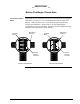
4.1 Mounting ST 3000 Transmitter, Bracket mounting, continued Continued Table 8 Mounting ST 3000 Transmitter to a Bracket, continued Step Action 4 Loosen set screw on outside neck of transmitter one full turn. Rotate Transmitter housing in maximum of 180 degree increment in left or right direction from center to position you require and tighten set screw (1.46 to 1.68 Nùm/13 to 15 lb-in). Example - Rotating Transmitter housing. 180 degrees max. Electronics Housing 180 degrees max.
4.1 Mounting ST 3000 Transmitter, The mounting position of a model STA122 or STA922 Absolute Pressure Transmitter or a model STD110 Draft Range Differential Pressure Transmitter is critical as the transmitter spans become smaller. A maximum zero shift of 2.5 mm Hg for an absolute transmitter or 1.5 in H2O for a draft range transmitter can result from a mounting position which is rotated 90 degrees from vertical. A typical zero shift of 0.12 mm Hg or 0.
4.1 Mounting ST 3000 Transmitter, Precautions for Mounting Transmitters with Small Absolute or Differential Pressure Spans, continued Continued For a transmitter with a small differential pressure span, you must ensure that the transmitter is vertical when mounting it. You do this by leveling the transmitter side-to-side and front-to-back. See Figure 6 for suggestions on how to level the transmitter using a spirit balance. You must also zero the transmitter by following the steps in Table 9 below.
4.1 Mounting ST 3000 Transmitter, Flange mounting ATTENTION Continued To mount a flange mounted transmitter model, bolt the transmitter’s flange to the flange pipe on the wall of the tank. On insulated tanks, remove enough insulation to accommodate the flange extension. Figure 7 shows a typical installation for a transmitter with the flange on the high pressure (HP) side so the HP diaphragm is in direct contact with the process fluid.
4.1 Mounting ST 3000 Transmitter, Flush mounting Continued To mount a flush mounted transmitter model, cut a hole for a 1-inch standard pipe in the tank or pipe where the transmitter is to be mounted. Weld the 1-inch mounting sleeve to the wall of the tank or to the hole cut on the pipe. Insert the meter body of the transmitter into the mounting sleeve and secure with the locking bolt. Tighten the bolt to a torque of 8.1 to 13.5 N · m (6 to10 lb-ft).
4.1 Mounting ST 3000 Transmitter, High Temperature Transmitter Mounting Continued You can mount the high temperature transmitter directly to the process flange connection or the process piping. Figure 9 shows typical pipe and flange mounted transmitter installations for comparison. To mount a flange mounted transmitter model, bolt the transmitter’s flange to the flange on the wall of the tank or process pipe.
4.1 Mounting ST 3000 Transmitter, Remote seal mounting ATTENTION Continued Use the procedure in Table 10 to mount a remote diaphragm seal transmitter model. Figure 10 shows a typical installation for a remote diaphragm seal transmitter for reference. Mount the transmitter flanges within the limits stated here for the given fill-fluid in the capillary tubes with a tank at one atmosphere. IF the fill fluid is… THEN mount the flange… Silicone DC 200 Oil no greater than 22 feet (6.
4.1 Mounting ST 3000 Transmitter, Remote seal mounting, continued Table 10 Continued Mounting Remote Diaphragm Seal Transmitter, continued Step Action 3 If Transmitter Model Number is… STR93D or STR12D STR13D Then Connect Remote Seal on… low pressure (LP) side of transmitter to upper flange mounting on tank wall for fixed or constant head H2. high pressure (HP) side of transmitter to upper flange mounting on tank wall for fixed or constant head H2.
4.2 Summary Piping ST 3000 Transmitter The actual piping arrangement will vary depending upon the process measurement requirements and the transmitter model. Except for flanged and remote diaphragm seal connections, process connections are made to ¼ inch or ½ inch NPT female connections in the process head of the transmitter’s meter body.
4.2 Piping ST 3000 Transmitter, Piping Arrangements, continued Continued Another piping arrangement uses a block-off valve and a tee connector in the process piping to the transmitter as shown in Figure 12. Figure 12 Typical Arrangement for ½” NPT Process Connection Piping Tank Wall 1/2" NPT Connection Block-off Valve Transmitter location Table 11 lists the mounting location for the transmitter depending on the process.
4.2 Piping ST 3000 Transmitter, ATTENTION Process connections Continued Care must be taken when installing transmitters on hot processes. The operating temperature limits for the device (as listed in Table 6) must not be exceeded. Impulse piping may be used to reduce the temperature of the process that comes into contact with the transmitter meter body. As a general rule there is a 56 degree C drop (100 °F) in the temperature of the process for every foot (305 mm) of ½ inch uninsulated piping.
4.2 Piping ST 3000 Transmitter, Continued Flange descriptions Table 13 describes the available flange connections for flange mounted liquid level transmitters. Table 13 Flange Description Transmitter Type Description Flush or Extended Diaphragm 2-inch 150# serrated–face flange with 4 holes 19 mm (3/4 in) diameter on 120.7 mm (4.75 in) diameter bolt circle and an outside diameter of 150 mm (5.91 in). 2-inch 150# serrated–face flange with 8 holes 19 mm (3/4 in) diameter on 127 mm (5.
4.2 Piping ST 3000 Transmitter, Continued Installing flange adapter Table 14 gives the steps for an optional flange adapter on the process head. ATTENTION Slightly deforming the gasket supplied with the adapter before you insert it into the adapter may aid in retaining the gasket in the groove while you align the adapter to the process head. To deform the gasket, submerse it in hot water for a few minutes then firmly press it into its recessed mounting groove in the adapter.
4.3 Summary Wiring ST 3000 Transmitter The transmitter is designed to operate in a two-wire power/current loop with loop resistance and power supply voltage within the operating range shown in Figure 13. Figure 13 Operating Range for ST 3000 Transmitters. 1440 1200 Loop Resistance (ohms) = Operating Area NOTE: A minimum of 250 0hms of loop resistance is necessary to support communications. Loop resistance equals barrier resistance plus wire resistance plus receiver resistance.
Wiring ST 3000 Transmitter, Summary, continued Barriers can be installed per manufacturer’s instructions for transmitters to be used in intrinsically safe applications. ST 3000 Transmitter Terminal Block Electronics Housing Electronics Housing Terminal Block SIGNAL - SIGNAL + Terminal Block + - METER + TEST L+ - Internal Ground Terminal 3-Screw Terminal Block + - + - SIGNAL Figure 14 Continued TEST 4.
4.3 Wiring ST 3000 Transmitter, Wiring connections ATTENTION Continued The procedure in Table 15 shows the steps for connecting power to the transmitter. For loop wiring and external wiring diagrams, refer to the installation drawings presented in Section 5. Detailed drawings are provided for transmitter installation in non-intrinsically safe areas and for intrinsically safe loops in hazardous area locations. If you are using the transmitter with Honeywell’s TPS system, see the previous TPS reference.
4.3 Wiring ST 3000 Transmitter, Approval body requirements Continued If your transmitter was ordered with Table III option 3N for selfdeclared approval per 94/9/EC (ATEX4), you must use a power supply that includes a voltage limiting device that will keep the voltage to the transmitter from exceeding 42 Vdc. You can achieve this by using a battery as the supply or one of these voltage limiting means. • Double wound mains transformer per BS 3535 or equivalent.
4.3 Wiring ST 3000 Transmitter, Conduit seal Continued Transmitters installed as explosionproof in a Class I, Division 1, Group A Hazardous (Classified) Location in accordance with ANSI/NFPA 70, the US National Electrical Code (NEC), require a “LISTED” explosionproof seal to be installed in the conduit, within 18 inches of the transmitter. Crouse-Hinds® type EYS/EYD or EYSX/EYDX are examples of “LISTED” explosionproof seals that meets this requirement.
4.3 Wiring ST 3000 Transmitter, Existing meter connections Continued Existing analog meters and SM 3000 Smart Meters can be connected to Release 300 transmitters. Examples of each meter type are shown below. Analog Meter 10 8 6 80 10 0 0 20 40 % 60 10 2 4 Smart Meter 0 % SM 3000 Smart Meter Connections —The smart meter (3-wires) can be connected remotely to a Release 300 transmitter.
Section 5 —Reference Drawings 5.1 Wiring Diagrams and Dimension Drawing List Contents This section contains external wiring diagrams for guidance in wiring the transmitter and remote meters in hazardous and nonhazardous locations. Tables listing the available dimension drawings for ST 3000 transmitters are provided for reference. External Wiring Diagrams These wiring diagrams are included in numerical order behind this section for wiring reference.
5.1 Wiring Diagrams and Dimension Drawings, Dimension Drawings Continued The tables on the following pages list available dimension drawings for reference. If you need a copy of a drawing, please determine the appropriate drawing number from the following tables and contact your Honeywell representative to obtain a copy.
5.
5.
Transmitter Type and Key Number Table Selections Mounting Angle Bracket (MB), (SB) Vertical Pipe Drawing Flat Bracket (FB) Horizontal Pipe Vertical Pipe Number Horizontal Pipe Remote Seals STR14A** – 51500415 – STR12D**, STR13D** Table I 2_ _ 51500414 51500412 51500399 1_ _, 3_ _ STR12D** Table I _ _D STR93D ** Table I 51500400 – 51500395 51500394 51500392 51500390 STR14G**, STR17G** – STR94G** 51500380 – – STR94G** ⇐ 51500378 51500385 ⇐ 51402418000 ⇐ 51500383 51500384 Ta
5.1 Wiring Diagrams and Dimension Drawings, Continued Dimension Drawings - Series 100 and Series 900, Continued Transmitter Type and Key Number **STR_ _ _ Table Selections Mounting Drawing Number – 51305141-000 Table II Flush Flange 3.5” diaphragm _ _ _A_ _ _ _ _ _ _ _ Off Line Flange 2.4” diaphragm _ _ _B _ _ _ _ _ _ _ 51305138-000 Off Line Flange 2.9” diaphragm _ _ _C _ _ _ _ _ _ _ _ 51305139-000 Off Line Flange 4.1” diaphragm _ _ _D _ _ _ _ _ _ _ _ 51305140-000 Extended Flange 2.
Appendix A Smart Meter Reference A.1 Introduction Smart Meter Option Depending upon your transmitter model, you can equip the ST 3000 transmitter with the Smart Meter option (option SM). This new integral smart meter is designed for ST 3000 Release 300 Transmitters and provides functionality not available with other smart meter designs.
A.2 Smart Meter Display Display description Figure A-1 Figure A-1 shows a smart meter display with all its indicators and segments lit for reference. Table A-1 shows a smart meter with the pushbuttons highlighted and a brief description of each pushbutton. The pushbuttons are used for setting up the smart meter display and making zero and span adjustments. Smart Meter Display with All Indicators Lit. 17-Segment Bargraph (0 to 100%) VAR SEL.
A.3 Smart Meter Specifications Operating Conditions and Specifications Table A-2 Before installing a transmitter equipped with a smart meter or installing the smart meter in an existing transmitter, please note the specifications and operating limits of the meter in Table A-2. Smart Meter Specifications.
A.4 Setting Range Values (Local Zero and Span) Local zero and span option ST 3000 Release 300 transmitters are available with optional local zero and span adjustments. This option is for applications that do not require an SFC nor digital integration with our TPS system. About local adjustments You must apply equivalent zero and span pressures to make the local zero and span adjustments. This is similar to setting the LRV and URV to applied pressures using the SFC.
A.4 Setting Range Values (Local Zero and Span), Continued Procedure, continued Table A-3 Setting Range Values Using Local Zero and Span Adjustments, Continued Step Action 3 Loosen end-cap lock and remove end-cap from PWA side of electronics housing to expose local zero and span assembly or smart meter with zero and span adjustments. Example – Local zero and span assembly. SPAN ZERO Example – Smart meter with zero and span adjustments. VAR SEL.
A.4 Setting Range Values (Local Zero and Span), Continued Procedure, continued Table A-3 Setting Range Values Using Local Zero and Span Adjustments, Continued Step 4 Action Turn ON transmitter power and let it warm up for a few minutes. Using an accurate pressure source, apply desired zero equivalent pressure to transmitter. ATTENTION For differential pressure transmitters, apply pressure to the high pressure head for positive range values or vent both heads to atmosphere for zero.
A.4 Setting Range Values (Local Zero and Span), Continued Procedure, continued Table A-3 Setting Range Values Using Local Zero and Span Adjustments, Continued Step 7 Action Using an accurate pressure source, apply pressure equivalent to desired upper range value to transmitter. ATTENTION For differential pressure transmitters, apply pressure to the high pressure head and be sure that the pressure to the low pressure head is at its reference value. 8 Check that milliammeter reading is 20 mA.
A.4 Setting Range Values (Local Zero and Span), Continued Procedure, continued Table A-3 Setting Range Values Using Local Zero and Span Adjustments, Continued Step Figure A-2 Action 10 Wait 30 seconds so that changes have been copied to the transmitter’s non-volatile memory. 11 Remove applied pressure and turn OFF transmitter power. 12 Replace end-cap on PWA side of electronics housing and tighten lock. 13 Remove milliammeter from TEST terminals and replace end-cap and tighten lock.
A.5 Configuring Smart Meter Using Pushbuttons Using Pushbuttons on Meter to Configure Smart Meter Display The smart meter can be set to show the PV out in engineering units that are appropriate for your process application. You can select an available engineering unit or enter a custom one including upper and lower display limit settings for the smart meter’s digital readout using buttons on the face of the meter.
A.5 Configuring Smart Meter Using Pushbuttons, Transmitter Output Conformity and Smart Meter Configuration, continued Continued • If you select pressure type engineering units, you cannot set the lower or upper display limits. These values are automatically set when you select the engineering units. • You can set only the upper display limit when the transmitter is configured for SQUARE ROOT output conformity.
A.5 Configuring Smart Meter Using Pushbuttons, Selecting Engineering Units WARNING Table A-5 Step Continued The procedure in Table A-5 outlines the steps for selecting the desired engineering units for a smart meter using its local adjustments on the face of the meter. You will be selecting the unit of measurement that you want the smart meter to indicate during normal operation. When the transmitter’s end-cap is removed, the housing is not explosionproof.
A.5 Configuring Smart Meter Using Pushbuttons, Continued Selecting Engineering Units, continued Table A-5 Step 4 Selecting Engineering Units, continued Action Meter Display Press UNITS SET button to lock in selected code. ATTENTION If you select an invalid code according to the selections in Step 3, the meter display will show an error code Er1 for one second and then return to the previous engineering units selection. VAR SEL. UPPE R VALUE % 0 100 0.
A.5 Configuring Smart Meter Using Pushbuttons, Setting Lower and Upper Display Values Table A-6 Continued The Table A-6 shows the restrictions on setting the display values for given engineering units and output conformity selections.
A.5 Configuring Smart Meter Using Pushbuttons, Continued Setting Lower Display Values, continued Table A-7 Setting Lower Display Values for Smart Meter Display Step 1 Action You have completed units selection in Table A-5 and U-L appears on the display. Press LOWER VALUE button to initiate lower display limit setting function. Meter Display If lower limit display value was previously set, KNOWN VALUE indicator lights and set value flashes in display. VAR SEL.
A.5 Configuring Smart Meter Using Pushbuttons, Continued Setting Lower Display Values, continued Table A-7 Step 3 Setting Lower Display Values for Smart Meter Display, continued Action Press Increase button to call up next available magnitude range selection or Decrease button to call up previous magnitude range selection. NOTE: This action enables the multiplier (K) for indicating larger ranges and shifts the decimal point of the digital display left or right depending on which button is pushed.
A.5 Configuring Smart Meter Using Pushbuttons, Continued Setting lower display values, continued Table A-7 Setting Lower Display Values for Smart Meter Display, continued Step Action 5 Press Increase button to select the next available digit value or Decrease button to select the previous digit value. Repeat this action until desired value is on display. 6 Meter Display First digit value setting. VAR SEL.
A.5 Configuring Smart Meter Using Pushbuttons, Continued Setting lower display values, continued Table A-7 Setting Lower Display Values for Smart Meter Display, continued Step Action 9 Press Increase button to select the next available digit value or Decrease button to select the previous digit value. Repeat this action until desired value is on display. Meter Display Third digit value setting. VAR UPPE R SEL.
A.5 Configuring Smart Meter Using Pushbuttons, Setting Upper Display Values ATTENTION Table A-8 Continued The procedure in Table A-8 outlines the steps for setting the upper display limit to represent the 100 percent (URV) output of the transmitter. This procedure applies only for Flow units (GPM or GPH) in a transmitter configured for SQUARE ROOT output conformity, or CUSTOM unit in a transmitter configured for linear or square root output conformity.
A.5 Configuring Smart Meter Using Pushbuttons, Continued Setting Upper Display Values, continued Table A-8 Step 3 Setting Upper Display Value for Smart Meter Display, continued Action Press Increase button to call up next available magnitude range selection or Decrease button to call up previous magnitude range selection. NOTE: This action enables the multiplier (K) for indicating larger ranges and shifts the decimal point of the digital display left or right depending on which button is pushed.
A.5 Configuring Smart Meter Using Pushbuttons, Continued Setting Upper Display Values, continued Table A-8 Setting Upper Display Value for Smart Meter Display, continued Step Action 5 Press Increase button to select the next available digit value or Decrease button to select the previous digit value. Repeat this action until desired value is on display – use 9 for example purposes. Meter Display First digit value setting is set to 9. VAR SEL.
A.5 Configuring Smart Meter Using Pushbuttons, Continued Setting Upper Display Values, continued Table A-8 Step 8 Setting Upper Display Value for Smart Meter Display, continued Action Meter Display Press UPPER VALUE button to lock-in second digit and activate next active digit. Readout now displays next active digit which will be zero unless upper value was set before. VAR SEL.
A.5 Configuring Smart Meter Using Pushbuttons, Continued Setting Upper Display Values, continued Table A-8 Step Setting Upper Display Value for Smart Meter Display, continued Action 12 Press UPPER VALUE button to lock-in “1” digit and activate sign segment. 13 Press Increase button to set sign segment to minus sign for negative values or Decrease button to set it to BLANK. for positive values.
A.6 Configuring Smart Meter Using SFC Using the SFC to Configure the Smart Meter Display You can select an available engineering unit or enter a custom one including upper and lower limit settings for the smart meter’s digital readout using the SFC.
A.6 Configuring Smart Meter Using SFC, Transmitter Output Conformity and Smart Meter Configuration, continued • Continued You can set both the lower and upper display limits when you have selected custom engineering units (Custom) and the transmitter output conformity is set to LINEAR.
A.6 Configuring Smart Meter Using SFC, Continued Procedure, continued Table A-9 Setting Up Smart Meter Configuration Using an SFC, continued Step Press Key 3 NON-VOL ENTER (YES) Read Display or Action M e t e r S F C M e t M e t C o n W O R K e r e r I i g N G . C o n P B d f f Description . . i g Enters meter configuration function and confirms that smart meter is present. Timed prompt - Proceed to Step 4.
A.6 Configuring Smart Meter Using SFC, Continued Procedure, continued Table A-9 Setting Up Smart Meter Configuration Using an SFC, continued Step Press Key 5 NON-VOL ENTER (YES) Read Display or Action M e " t e r E n g U n i Description t s H 2 O _ 3 9 F MmHg_0C DECONF I MENU ITEM PSI KPa MPa Calls up present meter Engineering Unit selection. (Note that unit “H2O_39F is shown for example purposes only.) Repeatedly press [MENU ITEM] key to step through other selections.
A.6 Configuring Smart Meter Using SFC, Continued Procedure, continued Table A-9 Setting Up Smart Meter Configuration Using an SFC, continued Step Press Key 7 NON-VOL ENTER (YES) Read Display or Action M e t e S F C M e D a t r E n g W O R K I t e r a D o w n E n g S F C E U U n i N G . E n g . t s . U n i t s l o a d e d Selected engineering unit is downloaded to transmitter and high/low display limit setting function is initiated.
A.6 Configuring Smart Meter Using SFC, Continued Procedure, continued Table A-9 Setting Up Smart Meter Configuration Using an SFC, continued Step Press Key 11 NON-VOL ENTER (YES) Read Display or Action E U L o E N T E R E D E n g U n i E N T E R 12 NON-VOL ENTER (YES) E n g S F C t M e t 13 NON-VOL ENTER (YES) M e t M e M t r N G . U n i t s 14 D o w n i r r t e r N o t e r i H i - L o f E n g D o w n U n i e t s .
A.7 Configuring Smart Meter Using SCT 3000 Using the SCT to Configure Smart Meter Display You can select an available engineering unit or enter a custom one including upper and lower limit settings for the smart meter’s digital readout using the SCT 3000. To configure the smart meter using the SCT, click on the Local Meter tab in the ST 3000 device window. Use the information fields on the tab to select and enter the engineering unit and lower and upper display limits, if applicable.
A.8 Typical Smart Meter Indications Typical operation indications Table A-10 Table A-10 summarizes typical smart indications. meter Note that other combinations of status messages are possible. Summary of Typical Smart Meter Indications. Meter Indication What It Means Meter Indication What It Means No power applied. % 0 % 0 100 100 - - - 0 % 20 0 ANALOG 100 Normal display for transmitter in Analog mode with digital readout in inches of water.
A.8 Typical Smart Meter Indications, Operation error codes Table A-11 Continued Table A-11 identifies possible meter error codes and what they mean. Smart Meter Error Codes and Descriptions. If error indication is . . . Then, it means You have tried to set local Zero or Span adjustment in a Series 100 transmitter that does not support this option. VAR SEL. UPPE R VALUE 0 % Er 0 100 UNITS % ANALOG SET LOWER VALUE VAR SEL.
A.8 Typical Smart Meter Indications, Continued Operation error codes, continued Table A-11 Smart Meter Error Codes and Descriptions, continued. If error indication is . . . Then, it means You have tried to set a span value that is outside acceptable limits for your transmitter. VAR SEL. UPPE R VALUE 0 % 100 UNITS Er 4 % ANALOG LOWER VALUE VAR SEL.
Appendix B —Hazardous Locations Reference Reference Information B.1 Information is provided to clarify the Hazardous Location installation requirements in North America and internationally. An explanaition of the applicalbel enclosure classification systems is also provided.
B.1 North American Classification of Hazardous Locations, Continued Examples Given the above criteria, the following examples are made: • A Class III, Division 1 location is a location in which easily ignitable fibers or material processing combustible flyings are handled, manufactured or used. • A Class III, Division 2 location is a location in which easily ignitable fibers are stored or handled.
B.1 North American Classification of Hazardous Locations, Continued Methods of Protection Protection Concept The following table summarizes available methods of protection for use in given locations. Designation Permitted Use Principle Explosionproof XP Division 1 & 2 Contains explosion and quenches flame. Intrinsic Safety IS Division 1 & 2 Limit energy of sparks under normal and fault conditions. Pressurized Type X and Y Division 1 Keeps flammable gas out.
B.1 Apparatus Parameters North American Classification of Hazardous Locations, Continued The Intrinsically Safe Apparatus Parameters are defined as follows. Parameter Description Vmax Maximum safe voltage which can be applied to the apparatus terminals. Imax Maximum safe current which can be applied to the apparatus terminals. Ci Unprotected capacitance in the apparatus which can be considered present at the terminals.
B.1 North American Classification of Hazardous Locations, Continued Entity Concept Under entity requirements, the concept allows interconnection of intrinsically safe apparatus to associated apparatus, not specifically examined in such combination.
B.1 North American Classification of Hazardous Locations, Continued Table B-1 Factory Mutual (FM) Approval, Continued Intrinsic Safety Entity Parameters (1) Class I, II, III, Divisions 1 and 2, Groups A - G VMax ≤ 42.4 V IMax = 225 mA PMax = 1.2 W Ci = 4.2 nF (1) Li = 0 With no integral indicator, or with integral Smart Meter, option SM. Li = 150 µH With Analog Meter, option ME. Install in accordance with Honeywell drawing 51204241.
B.2 About IEC International Electrotechnical Commission (IEC) Classification of Hazardous Locations The IEC has established a number of recommendations applying to the construction of explosion protected electrical apparatus identified. These recommendations are found within IEC 79-0 through 79-15 and 79-28.
B.2 International Electrotechnical Commission (IEC) Classification of Hazardous Locations, Continued IEC Methods of Protection Protection Concept The following table summarizes available methods of protection for use in given locations. Designation Permitted Use Principle Flameproof d Zone 1 & 2 Intrinsic Safety ia Zone 0, 1 & 2 Limits energy of sparks under 2 faults. ib Zone 1 & 2 Limits energy of sparks under 1 fault Pressurized p Zone 1 Keeps flammable gases out.
B.2 International Electrotechnical Commission (IEC) Classification of Hazardous Locations, Continued IEC Temperature Classification Equipment intended for installation directly within the hazardous location must also be classified for the maximum surface temperature that can be generated under normal or fault conditions as referenced to the maximum operating ambient of the equipment.
B.2 International Electrotechnical Commission (IEC) Classification of Hazardous Locations, Continued Certification and Conformity Details, continued Table B-4 Standards Australia (LOSC) Certification Code 4H Description Intrinsically Safe Ex ia IIC T4 Class I Zone 0. Flameproof Ex d IIC T6 Class I Zone 1 Non-Sparking Apparatus - Type of Protection ‘n’ Ex n IIC T6 Class I Zone 2 LOSC Intrinsic Safety Parameters (1) Ui = 42.4 V Ii = 225 mA Pi = 1.2 W Ci = 4.
B.3 Enclosure Ratings NEMA and IEC Recognition The NEMA (National Electrical Manufacturer’s Association) enclosure classifications are recognized in the US. The IEC Publication 529 Classifications are recognized throughout Europe and those parts of the world that use the IEC standards as a basis for product certifications. The following paragraphs provide a discussion of the Comparison Between NEMA Enclosure Type Numbers and IEC Enclosure Classification Designations.
B.3 Enclosure Ratings, Continued IEC Designations, continued Table B-6 provides an approximate conversion from NEMA enclosure type numbers to IEC enclosure classification designations. The NEMA types meet or exceed the test requirements for the associated IEC classifications; for this reason the Table cannot be used to convert from IEC classifications to NEMA types.
Index Flange mounted, 23 Flat mounting bracket, 23 Flow engineering units Smart meter, 58 Flush mounted transmitter, 30 A Analog meter connections, 44 Analog mode, 7, 10, 13, 21 Angle mounting bracket, 23 G B Ground External ground, 42 Ground terminal, 39 Barriers, 40 Battery pack, SFC Installing and charging, 20 Bench check, 5 Blow-down lines, 34, 37 Bracket mounting Horizontal pipe, 24 Vertical pipe, 24 H Hazardous locations reference, 82 IEC Classifications, 88 North American Classifications, 82 C
Index R T Remote seal mounting, 32 S Series designations, 2 Setting range values using local zero and span adjustments.
Addendum to ST 3000 Smart Transmitter Release 300 and SFC Smart Field Communicator Model STS 103 Installation Guide 34-ST-33-39 Overview Two new models have been added to the family of ST3000 Smart Transmitters: Gauge Pressure Model STG19L Gauge Pressure Model STG99L. Each of these has an Upper Range Limit (URL) of 10000 psi (690 bar), which is significantly higher than previously available models.
Additions to the User Manual The additions to User Manual 34-ST-33-39 that relate to the new Gauge Pressure transmitter models are given in Table 1 of this addendum. Use the information in Table 1 to reference and annotate your Installation Guide. Table 1 – Additions to the User Manual Page # in User Manual 18 Sub-Section 3.1 Considerations for ST 3000 Transmitter Temperature Limits Table 5 Operating Temperature Limits (Transmitters with Silicone Fluid Fill Fluids) 19 3.
Exhibit B –Additions to Table 6 Transmitter Type Upper Range Limit (URL) Maximum Working Pressure Rating Overpressure Rating Draft Range 10 inches H2O (25 mbar) 50 psi (3.5 bar) 50 psi (3.5 bar) (No overpressure protection is provided) Differential Pressure 400 inches H2O (1 bar) 3000 psi (210 bar) 3000 psi (210 bar) 100 psi (7 bar) 3000 psi (210 bar) 3000 psi (210 bar) 3000 psi (210 bar) 3000 psi (210 bar) 3000 psi (210 bar) 100 psi (7 bar) 100 psi (7 bar) 150 psi (10.
Exhibit C –Additions to Dimension Drawings Dimension Drawings - Series 100 and Series 900, Continued Transmitter Type and Key Number Table Selections Mounting Angle Bracket (MB), (SB) Vertical Pipe STG944, STG974 See Key Number Horizontal Pipe 51500411 Column Vertical Pipe See Key Number STA122, STA140 Column 51500362 STA922, STA940 51500359 51500373 51500363 STG90L, STG94L, STG97L, 51500377 STG14T (High Temperature) 4/02 51500370 ⇐ ⇐ 51500375 51500376 STG98L, STG99L ⇐ ⇐ 51500371
ST 3000 Smart Transmitter Release 300 and Smart Field Communicator Model STS103 Transmitter Models: STD110, STD120, STD125, STD130, STD170, STD924, STD930 Overview 34-ST-99-25 10/04 Addendum (to Installation Guide 34-ST-33-39) Replacement Meterbody and Heads The ST 3000 Pressure Transmitter, Models: • • STD110, STD120, STD125, STD130, and STD170 STD924 and STD930 with optional Tantalum or Monel diaphragm is now being shipped with newly designed meter body and process heads.
Additions to the Installation Guide The additions to Installation Guide 34-ST-33-39 that relate to the newly designed meter body and process heads are given in Table 1 of this addendum. Use the information in Table 1 to reference and annotate your User Manual. Table 1 – Additions to the User Manual Page # in User Manual 19 Sub-Section 3.
Figure 1 ST 3000 Model STD110, STD120, STD125, STD130, STD170, STD924, STD930 (Rev S or greater) 10/04 34-ST-99-25 (Addendum to 33-ST-33-39) 3 of 4
Dimension Drawings The following table provides references to dimension drawings for newly designed ST 3000 Pressure Transmitters (Revision S and greater). If you need a copy of a drawing, please determine the appropriate drawing number from the following table and contact your Honeywell representative.
34-ST-99-36 10/04 ST 3000 Smart Pressure Transmitter, Release 300 and Smart Communicator Model STS 103 Overview Addendum (to Installation Guide 34-ST-33-39) ATEX Directive 94/6/EC The ATEX Directive 94/6/EC is a European CE Mark directive concerning products that are designed for use in potentially explosive environments. This “New Approach” directive is based on, and is an expansion of, European Norms (EN, CENELEC standards).
Purpose and Content of this Addendum This Addendum includes information required under the ATEX Directive regarding: 1. The appearance and meaning of each certification mark (CE Mark) that appears on the label(s) affixed to the product. 2. Instructions for installation and use of the product.
Marking, ATEX Directive Honeywell’s Model ST 3000 Smart Pressure Transmitter, with the following nameplates attached, has been certified to comply with Directive 94/9/EC of the European Parliament and the Council as published in the Official Journal of the European Communities No. L 100/1 on 19-April-1994.
Nameplate 51452618-001, nA, 4-20 mA / DE, is mounted on the enclosure. The following is a representation of this nameplate: Nameplate 50003885-001, 4-20 mA / DE, multiple certification nameplate.
Specific Parameters for Intrinsic Safety Field wiring terminals, (+ , –): Ui = 30 V, Ii = 100 mA, Pi = 1.2 W Without local analog meter, ME: Ci = 4.2 nF, Ri = 0, Li = 0 With local analog meter, ME: Ci = 4.2 nF, Ri = 0, Li = 150 µH With local smart digital meter, SM: Ci = 4.2 nF, Ri = 0, Li = 0 Special conditions for safe use, The pressure transmitter is an intrinsically safe apparatus that can be installed in potentially explosive atmospheres.
Specific Parameters for Non-Sparking Zone 2 Installation (Honeywell certified) Supply Voltage: 11-42 Vdc Supply Current: 23 mA Ambient Temperate Limits: - 50oC to 93oC Temperature Classification: T6 at Ta ≤ 78oC o T5 at Ta ≤ 93 C Special Conditions for Safe Use, Non-Sparking Zone 2 Installation (Honeywell certified) • The installation of this equipment in Zone 2 hazardous areas must comply with VDE specification 0165, IEC 60079-14, EN 50021 and/or valid national standards for installation and ope
51452504, Revision B DECLARATION OF CONFORMITY ATEX 0344 We declare under our sole responsibility that the following products, ST 3000 Smart Pressure Transmitters, Series 100 and 900, Release 300 (per attached list) to which this declaration relates, are in conformity with the protection requirements of Council Directive: 94/9/EC (ATEX Directive) on the approximation of the laws of the Member States concerning equipment and protective systems intended for use in potentially explosive atmospheres, and 8
ST3000, R300 Pressure Transmitters Certificate Protection Model LCIE 02 ATEX 6099 Ex II 2 G, EEx d IIC, T6 or T5 LCIE 02 ATEX 6100X Ex II 2 G, EEx ia IIC, T6 to T4 LCIE 02 ATEX 6101X Ex II 1 G, EEx ia IIC, T6 to T4 LCIE 03 ATEX 6175X Ex II 1 G, EEx ia IIC, T6 to T4 ST…-HC…-3S Model ST……-3D Description Factory 4-20 mA / DE / HART / Fieldbus Phoenix ST……-3S 4-20 mA / DE Phoenix ST…-HC…-3S 4-20 mA / HART Phoenix Foundation TM Fieldbus Phoenix Series Description STA122 STA140 100 10
Certificate of Manufacturer II 3 G EEx nA IIC ATEX This certificate applies to the following equipment: ST 3000 Smart Pressure Transmitters, Series 100 and 900, Release 100 and 900, 4-20 mA, DE, HART, and FOUNDATIONTM Fieldbus (per attached list) This equipment has no arcing or sparking parts and no ignition-capable hot surfaces, and therefore conforms to Clause 6.3.1.3 of VDE 0165/2.91, IEC 60079-14, and EN 50021 for operation in Zone 2 hazardous areas providing that the following conditions are observed.
ST3000, R300 Pressure Transmitters Model STA122 STA140 STD110 STD120 STD125 STD130 STD170 STF128 STF12F STF132 STF13F STF14F STF14T STG140 STG14L STG14T STG170 STG17L STG180 STG18L STR12D STR13D STR14A STR14G STR17G STA922 STA940 STD924 STD930 STD974 STF904 STF924 STF92F STF932 STF93F STG19L STG93P STG944 STG94L STG974 STG97L STG98L STG99L STR93D STR94G 10 of 10 Series 100 100 100 100 100 100 100 100 100 100 100 100 100 100 100 100 100 100 100 100 100 100 100 100 100 900 900 900 900 900 900 900 900 900 90
Industrial Measurement and Control Honeywell International, Inc. 2500 W.