
Barcode Reader User Manual
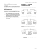

SUB SERIES INTERVAL DATA RECORDERS
3 62-0342—01
removed. The third-party meter IDR uses a DIP switch to
perform this function. This switch is preset at the factory and
requires no further adjustment.
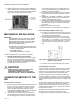
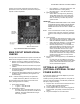
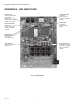
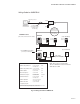
Fig. 5. Overview of main circuit board.
MAIN CIRCUIT BOARD VISUAL
CHECKS
Once you have connected meter #1 to jack #1 in the IDR, the
IDR should be energized. If the IDR is not energized, verify:
1. Meter #1 is turned on. (Meter #1 powers the IDR; if
Meter #1 is not installed and powered up, the IDR will
not function.)
2. Verify that JMP8 on the IDR circuit board has a jumper
installed.
3. Verify that J23 & J24 on the IDR circuit board are set in
the position labeled “MTR”. Both jumpers should be set
to the RIGHT position.
4. Verify that the cable between Meter #1 and Jack #1 on
the IDR is properly assembled. (See Appendix A for
cable assembly.)
NOTE: If the IDR is being powered by the optional AC
adapter instead of by Meter #1, see Section 5.0.
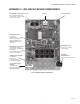
Verify the status of the LED indicators on the IDR circuit
board. (See Appendix B for locations.)
1. Power Supply Indicators
— L3, green -> This LED is ON.
— L1, green -> This LED is ON.
2. System status indicators
— D4 (CPU), red -> This LED flashes once per sec-
ond. If D4 flashes twice per second, the IDR is not
initialized. This will be addressed later using E-
Mon Energy software.
— D7 (Low Battery) -> This LED must be OFF. This
LED indicates a low or missing battery.
— D6 (System Error) -> This LED must be OFF.
3. Meter pulse indicators
— Yellow LEDs P1 through P8 may be flashing.
These LEDs indicate each meter’s pulse rate.
The flash rate depends on how much load the
meter is measuring. The faster the pulse the
greater the load.
IMPORTANT:
IF THE METER MEASURES ZERO LOAD, THERE
IS NO METER PULSE, WHEN THE PULSE RATE
IS ZERO THE YELLOW LED INDICATOR WILL
REMAIN EITHER ON OR OFF UNTIL THERE IS A
LOAD.
NOTE: If one of the LEDs does not flash, verify the meter
connection first. If the meter is properly connected,
check the meter’s display for a flashing load indica-
tor.
4. Panel Indicators
— Two LEDs are visible through the window on the
door of the stand-alone enclosure. THESE LEDS
ARE NOT PRESENT IN MMU STYLE IDRS.
— Green LED (Power Indicator) -> The green LED
indicates that power is present at the IDR.
— Red LED (Tamper Alarm) -> The red LED indi-
cates that the IDR door has been opened. This
tamper alarm LED will be on when the door is
closed, and will flash when the door is open.
When the software startup is performed, the IDR
will be initialized by the E-Mon Energy software
and the alarm LED will turn off as long as the door
remains closed. The alarm can only be reset
through the software.
5. IDR 16 Option 16 Card (applies only to the SUBIDR-16
model.)
— For each meter (9-16) installed on the options
card, another set of yellow LEDs (P9-P16) will be
present. These LEDs indicate the meter pulse
rate for meters #9 through #16.
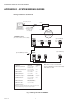
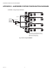
OPTIONAL AC ADAPTER
(OPTIONAL EXTERNAL 120 VAC
POWER SUPPLY)
If you are NOT using the optional AC adapter to power the
IDR, proceed to Section 6.0.
Instead of powering the IDR using Meter #1, Honeywell can
supply an optional AC adapter. If the IDR was provided with
this option, verify the following:
1. Jumpers J23 & J24 on the IDR circuit board are set to
the LEFT position (position labeled “EXT”.)
2. Jumper at JMP8 MUST be removed.
3. The AC adapter’s two-wire cord must be plugged into
the IDR at TB9. (The polarity of these wires does not
matter.)
4. Plug the AC adapter into a 120 VAC outlet.