
Phau Ntawv Qhia


3
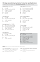
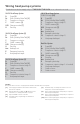
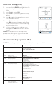
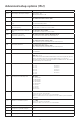
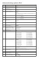
Wiring terminal designations
S
Universal input for
wired indoor or outdoor
sensors
L/A
- A
Heat Pump fault input (most
common case)
S
O/B Changeover valve
Y
Compressor contactor
(stage 1)
AUX -
W2
Auxiliary heat relay
Heat relay (stage 2)
Y2
Compressor contactor
(stage 2)
E Emergency Heat relay
G
Fan Relay W Heat relay (stage 1)
C
24VAC common. For 2
transformer systems,
use common wire from
cooling transformer.
K
Connect to K on Wire Saver
Module**
U
Unused
R
24VAC power from heating
transformer*
U
Rc
24VAC power from cooling
transformer*
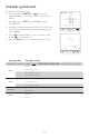
Note: Not all
terminals may be
used, depending
on the system
type that is being
wired. The most
commonly used
terminals are
shaded.
* Terminal can be jumped using Slider Tab. See “Setting Slider Tabs” above.
** The THP9045A1023 Wire Saver Module is used on heat/cool systems when you
only have four wires at the thermostat, and you need a fifth wire for a common wire.
Use the K terminal in place of the Y and G terminals on conventional or heat pump
systems to provide control of the fan and the compressor through a single wire—the
unused wire then becomes your common wire. See THP9045 instructions for more
information.
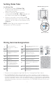
Set R Slider Tab.
• Use built-in jumper (R Slider Tab)
to differentiate between one or two
transformer systems.
• If there is only one R wire, and it is
connected to the R, Rc, or RH terminal, set
the slider to the up position (1 wire).
• If there is one wire connected to the R
terminal and one wire connected to the Rc
terminal, set the slider to the down position
(2 wires).
NOTE: Slider Tabs for U terminals should be
left in place for T6 Pro models.
Setting Slider Tabs
R/Rc slider tab
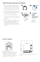
UWP Mounting System