
Install Instructions
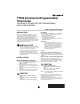
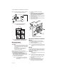
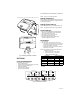
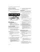
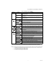
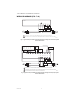

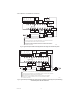
Table Of Contents

T7350 COMMERCIAL PROGRAMMABLE THERMOSTAT
62-0195—06 2
NOTE: Only TR21 models with no setpoint adjustment
can be used for temperature averaging.
Fig. 1. Typical location of thermostat
or remote-mounted sensor.
Fig. 2. Four TR21 sensors providing temperature
averaging network for T7350 Thermostat.
Mounting Subbase
The subbase mounts horizontally.
IMPORTANT
• When using the internal temperature or humidity
sensor, the device must be mounted horizontally
(with the LCD facing upwards). Precise leveling
is not needed.
• When using remote room temperature and
humidity sensors, thermostat mounting
orientation does not matter.
Wall mounting (using standard drywall screws) is
standard. Mounting to a 2 in. by 4 in. (50.8 mm by 101.6
mm) wiring box can be accomplished:
— for a horizontal box, no extra hardware is required.
— for a vertical box, part 209651A is required.
— Mount to European standard wall box (having 2.4 in.
(60.3 mm) between mounting screws in a horizontal
line) with or without adaptive hardware.
1. Position and level the subbase.
NOTE: A level wallplate is only for appearance.
The thermostat functions properly even
when not level.
2. Use a pencil to mark the mounting holes.
(See Fig. 3.)
3. Remove the subbase from the wall and drill two
3/16 in. (4.8 mm) holes in the wall (if drywall) as
marked. For firmer material such as plaster or
wood, drill two 7/32 in. (5.6 mm) holes.
4. Gently tap anchors (provided) into the drilled holes
until flush with the wall.
5. Position the subbase over the holes, pulling wires
through the wiring opening.
6. Loosely insert the mounting screws into the holes.
7. Tighten mounting screws.
Fig. 3. Mounting the subbase.
Mounting Thermostat on Subbase
(Fig. 4)
With the subbase installed, mount the thermostat:
1. Engage top subbase tabs into the thermostat top.
2. Swing the thermostat down.
3. Press the lower edge of the case to latch.
NOTE: To remove the thermostat from the wall, first pull
out at the bottom of the thermostat; then remove
the top.
Wiring
Follow equipment manufacturer wiring instructions when
available. Refer to the Wiring Diagram section starting on
page 8 for typical hookups. A letter code is located near
each terminal for identification.
IMPORTANT
All wiring must comply with local electrical codes
and ordinances.
NOTE: Maximum (and recommended) wire size is 18-
gauge. Do not use wire smaller than 22-gauge.
1. Loosen subbase terminal screws and connect
system wires.
2. Securely tighten each terminal screw.
3. Push excess wire back into the hole in the wall.
4. Plug the hole with nonflammable insulation to
prevent drafts from affecting the thermostat.
5 FEET
(1.5 METERS)
YES
NO
NO
NO
M4823A
M29184
T4 T3
TT
SUBBASE
TR21
TT
TR21
TT
TR21
TT
TR21
WIRES THROUGH WALL
WALL
ANCHORS
(2)
M19608
MOUNTING
HOLES
MOUNTING
SCREWS