
Brochure
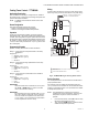
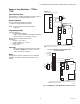
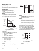
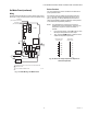
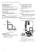

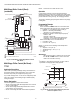
Table Of Contents
- TABLE OF CONTENTS
- T775 APPLICATION TIPS
- COMPATIBLE COMPONENTS
- FEATURES
- T775 OPERATIONS
- T775 APPLICATIONS
- Water Source Heat Pump Loop Water Controller - T775B
- Chiller - T775B
- Chiller, Rotary Compressor - T775B
- Cooling Tower Control - T775B2040
- Time-based Control of Fan, Pump, etc. - T775 (all models)
- Damper or Valve Modulation - T775M or T775R
- Hot Water Reset - T775R
- Chilled Water Reset - T775R
- Multi-Stage Boiler Control (No Reset) - T775P
- Multi-Stage Boiler Control (Reset) - T775P
- Multi-Stage Boiler Control (Reset) (continued)
- Multi-Stage Chiller Control (No Reset) - T775P
- 4 Stage with Pump Output and Reset - T775P using a T775S Expansion Module
- 4 Stage with Pump Output and Reset (continued)
- 3 Stage Reciprocating Chiller - T775L
- 4 Stage Heat and 6 Stage Cool - T775L
- 4 Stage Heat and 6 Stage Cool (continued)
- Pressure with a Variable Frequency Drive (VFD) - T775U
- Carbon Dioxide (CO2) Sensing - T775U
- T775 APPLICATION REPLACEMENT EXAMPLES
- T775M2030 Replacement for W973A Logic Panel
- T775M2030 Replacement for W973A Logic Panel (continued)
- T775M2030 Replacement for W973A Logic Panel (continued)
- T775R Replacement for W964F Aquatrol Panel with Floating Actuator
- T775R Replacement for W964F Aquatrol Panel with Floating Actuator (continued)
- T775R Replacement for W964F Aquatrol Panel with Floating Actuator (continued)
- T775L Replacement for S984 Step Controller
- T775L Replacement for S984 Step Controller (continued)
- T775L Replacement for W7100C Discharge Air Controller
- T775L Replacement for W7100C Discharge Air Controller (continued)
- T775L Replacement for W7100C Discharge Air Controller (continued)
- T775 CROSS REFERENCE
- NOTES

T775 SERIES 2000 ELECTRONIC STAND-ALONE CONTROLLERS
63-7147—3 12
Time-based Control of Fan, Pump, etc. –
T775 (all models)
Application Description
In this example, the T775B is able to energize a fan, pump,
lights, economizer, or other device based on a daily time
schedule rather than based on temperature.
Operation
In this example, one relay will energize at 6:00 a.m. and de-
energize at 6:00 p.m. daily to operate a fan, pump, or anything
at all.
Configuration Example
Place a 1,000 Ohm resistor at Sensor B (to simulate a
constant 32° F (0° C) temperature reading).
Wire the device to the normally open contacts on a relay.
Relay 1 is used in this example. See Fig. 7
Programming Example
Program in Setup for:
— Outputs
Options
Use Scheduler = YES
Program in Schedule for:
— Options
Set Date = current date
1
Set Time = current time
Set Daylight = YES or NO
— Mon-Fri
E1 Setpoint = Setpoint
E1 Time = 06:00 AM
E2 Setpoint = Setback
E2 Time = 6:00 PM
Relay 1: Control the device (fan, pump, etc.)
Program for:
— Setpoint = 0° F (-17° C)
— Differential = 1° F (-17° C)
— Sensor = Sensor B
— Setback =100° F (38° C)
— Action = Cool
Now the relay will close at 6:00 a.m. and open at 6:00 p.m.,
daily.
1
The Date must be set before the Time is set.
NOTE: Keep in mind that if the scheduler is energized, all
relays will follow the time schedule. If you do not
want some outputs to go into a setback mode,
choose Scheduler = NO for those outputs, or
program the setpoint and setback to the same
temperature.
IMPORTANT
After the desired value is selected, be sure to press
the # or $ or HOME button in order to save that
value in the controller’s memory.
Wiring
All output relays should have a common power wiring source,
which may or may not be the same as the T775 power wiring.
Fig. 7. T775B Wiring for time-based fan, pump or other
device.
M28021
T775B
C
NO
NC
C
NO
NC
C
NC
NO
C
NC
NO
T
T
120 VAC
C
+
RELAY
3
RELAY
2
RELAY
1
RELAY
4
120
COM
240
SENSOR B
T
T
FAN,
PUMP,
LIGHTS,
ECONOMIZER,
OR
OTHER DEVICE
L1
(HOT)
L2
1
1
INSERT 1000 OHM RESISTOR.
3
2
24 VAC POWER TERMINAL BLOCK.
POWER WITH 24 VAC OR 120/240 VAC AT THE APPROPRIATE
TERMINAL BLOCK.
3
2