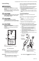
T775A/B/M Series 2000 Electronic Stand-Alone Controllers INSTALLATION INSTRUCTIONS PRODUCT DESCRIPTION The T775 electronic stand-alone controllers are the next generation of commercial and agricultural controls capable of remote sensing of temperature and providing switched and/or proportional outputs to various types of loads. Five models have analog (modulating) outputs for actuator and motor control, and NEMA-4 weatherproof enclosures are available for wet environments.
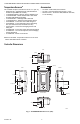
T775A/B/M SERIES 2000 ELECTRONIC STAND-ALONE CONTROLLERS Temperature Sensorsa Accessories The controller accepts 1,097 Ohms PTC at 77° F (25° C): • 50021579-001 – Standard sensor (included with all models except NEMA 4X models) • T775-SENS-STRAP– Strap on sensor withwiring box • T775-SENS-WR – Water resistant with 5 foot leads (included with NEMA 4X models) • T775-SENS-WT – Watertight with 6 foot lead • T775-SENS-OAT – Outdoor air temperature sensor • C7031B2005 – 6 inch duct mount with wiring box • C703
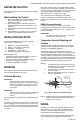
T775A/B/M SERIES 2000 ELECTRONIC STAND-ALONE CONTROLLERS BEFORE INSTALLATION Review the “Specifications” on page 35 before installing the controller. When Installing This Product 1. 2. 3. 4. Read these instructions carefully. Failure to follow them could damage the product or cause a hazardous condition. Check ratings given in instructions and on the product to ensure the product is suitable for your application. Installer must be a trained, experienced service technician.
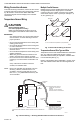
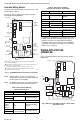
T775A/B/M SERIES 2000 ELECTRONIC STAND-ALONE CONTROLLERS Wiring Connections Access Multiple Parallel Sensors Multiple sensors can be parallel-series wired to sense average temperatures in large spaces. To maintain control accuracy, the number of sensors to be parallelseries wired must be of the n2 power (for example, 4, 9, 16, etc.) (See Fig. 3). To access the wiring connections, remove the two screws on the left side of the enclosure and gently swing open the top.
T775A/B/M SERIES 2000 ELECTRONIC STAND-ALONE CONTROLLERS Controller Wiring See Fig. 7 on page 6 for locating the appropriate power input, remote sensors input, low voltage, contact closure, and load output terminals. WARNING Electrical Shock Hazard. Can cause severe injury, death or property damage. Disconnect power supply before beginning wiring, or making wiring connections, to prevent electrical shock or equipment damage.
T775A/B/M SERIES 2000 ELECTRONIC STAND-ALONE CONTROLLERS Controller Wiring Details The wiring connection terminals are shown in Fig. 7 and are described in Table 2. Table 2. Description of Wiring Terminal Connections.
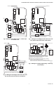
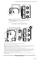
T775A/B/M SERIES 2000 ELECTRONIC STAND-ALONE CONTROLLERS SENSOR A SENSOR A T T T T L1 (HOT) 24 VAC L2 LOAD 4 NO COM LOAD 2 COM NO NO C NC + NO COM NO C NC 1 NC C NO NO C NC NO C NC LOAD 3 LOAD 2 LOAD 1 LOAD 4 COM NO LOAD 3 120V COM NC C NO COM NO NC C NO NC C NO COM NO LOAD 1 C + 120 COM 240 C M24476A Fig. 9. Wiring for Four-Stage Control – 24 Vac Input and 24 Vac Load. 1 FOR 240 VAC LOAD, CONNECT TO 240 TERMINAL. M24478A Fig. 11.
T775A/B/M SERIES 2000 ELECTRONIC STAND-ALONE CONTROLLERS HONEYWELL ELECTRONIC SERIES 90 MODUTROL MOTOR ML7984 ACTUATOR T1 T2 C B R W POWER OUTPUT 1 MODULATING OUTPUT TERMINAL (MOD 1) T1 T2 B RW 1 POWER OUTPUT B R– W+ B R– W+ 2 MODULATING OUTPUT TERMINAL (MOD 1) M27228 Fig. 13. Wiring for ML7984 Valve Actuator (Using 4 to 20 mA Signal). B R W – + B R W – + 3 1 TO VERIFY OUTPUT, TEST OPEN CIRCUIT VOLTAGE BETWEEN THE MOD 1 TERMINALS W AND R. - MINIMUM (DRIVE CLOSED) SIGNAL LESS THAN 0.
T775A/B/M SERIES 2000 ELECTRONIC STAND-ALONE CONTROLLERS M9184 OR M9185 MODUTROL MOTOR L1 (HOT) 1 L2 R W B R– W+ B R– W+ TR TR B 2 M9184 OR M9185 MODUTROL MOTOR 3 R W TR TR B M9184 OR M9185 MODUTROL MOTOR MODULATING OUTPUT TERMINAL (MOD 1) R W TR TR B 1 POWER SUPPLY. PROVIDE DISCONNECT MEANS AND OVERLOAD PROTECTION AS REQUIRED. 2 USE A 1300 OHM RESISTOR FOR TWO MOTORS, 910 OHM RESISTOR FOR THREE MOTORS.
T775A/B/M SERIES 2000 ELECTRONIC STAND-ALONE CONTROLLERS CHECKOUT Inspect all wiring connections at the controller terminals, and verify compliance with the installation wiring diagrams. WARNING Electrical Shock Hazard. Can cause severe injury, death or property damage. Disconnect power supply before beginning wiring or making wiring connections, to prevent electrical shock or equipment damage. If any wiring changes are required, first be sure to remove power from the controller before starting work.
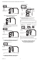
T775A/B/M SERIES 2000 ELECTRONIC STAND-ALONE CONTROLLERS INTERFACE OVERVIEW Menu Button The T775A/B/M controllers use an LCD panel and 6-button keypad to provide status information and permit user input of the programming, setup, and scheduling parameters. • Pressing the MENU button always displays the Program menu. If you are in Setup mode, you exit setup and return to the Program menu. • Pressing and holding the MENU button for five seconds leaves the current screen and displays the Setup menu.
T775A/B/M SERIES 2000 ELECTRONIC STAND-ALONE CONTROLLERS Accessing the Menus HOME RELAYS 1 2 3 4 ON Menus are used for programming, scheduling, viewing the summary settings, and setup of advanced options. SENSORS SENSOR A Programming, Scheduling, and Summary Menus To access these menus from the home screen, press the MENU button (See Fig. 24).
T775A/B/M SERIES 2000 ELECTRONIC STAND-ALONE CONTROLLERS 1. PROGRAMMING The controller must be programmed before being placed into service. IMPORTANT During programming, the controller is live at all times. For example, the contacts may open and close when adjusting the setpoint. Heating Mode Setpoint and Differential In heating mode, the differential is below the setpoint. The relay de-energizes when the temperature rises to the setpoint.
T775A/B/M SERIES 2000 ELECTRONIC STAND-ALONE CONTROLLERS Programming the T775A/B/M Controller To program the controller, perform the following procedures in the order listed: 1. Enter Program mode — see “1.1. Entering Program Mode” 2. Program the Outputs — see “1.2. Program Menu for Outputs” on page 14 MENU PROGRAM MENU PROGRAM 1.1. Entering Program Mode MENU PROGRAM OR MOD 1 MOD 2 RELAY 1 RELAY 2 RELAY 3 RELAY 4 EXIT When programming is complete, you may continue with “3.
T775A/B/M SERIES 2000 ELECTRONIC STAND-ALONE CONTROLLERS PROGRAM RELAY 1 DIFFRNTL MENU PROGRAM RELAY 1 DIFFRNTL 20 1.2.2. DIFFERENTIAL or THROTTLING RANGE Differential is used for Relay outputs and Throttling Range is used for Modulating outputs. oF ENTER DIFFERENTIAL FOR RELAY 1 M24495 Fig. 29. Program - Differential or Throttling Range. 1. From the menu, use the S and T buttons to highlight THROT RNG or DIFFERNTL. 2. Press the X button to display the throttling range value. 3.
T775A/B/M SERIES 2000 ELECTRONIC STAND-ALONE CONTROLLERS PROGRAM RELAY 1 SETBACK MENU PROGRAM RELAY 1 SETBACK 60 ENTER SETBACK SETPOINT FOR RELAY 1 1.2.5. SETBACK The Setback temperature option displays if scheduling is enabled (See Fig. 55 on page 24) or the DI Option is set to Setback. (See Fig. 57 on page 25). This is the desired setpoint temperature that you want to use during setback mode for this output.
T775A/B/M SERIES 2000 ELECTRONIC STAND-ALONE CONTROLLERS 2. SETUP (ADVANCED OPTIONS) Setup provides the ability to change the factory default settings for the temperature sensors and outputs, to enable/disable reset control, and to enable/disable scheduling. NOTE: The controller interface is intuitive. You may find that you do not need the following setup instructions for the sensors and outputs.
T775A/B/M SERIES 2000 ELECTRONIC STAND-ALONE CONTROLLERS SETUP SENSORS SENSOR A 2.2.2. SENSOR A SETUP SENSORS SENSOR A 1. From the Sensors menu, highlight SENSOR A. 2. Press the X button to display the Sensor A selections. UNITS CALIBRATE LABEL EXIT M24502 Fig. 36. Setup - Sensors - Sensor A Menu. SETUP SENSORS SENSOR A UNITS 2.2.2.1. UNITS (° F or ° C) SETUP SENSORS SENSOR A UNITS IMPORTANT This is a global change and affects the unit values for all temperature parameters on all displays.
T775A/B/M SERIES 2000 ELECTRONIC STAND-ALONE CONTROLLERS 2.2.2.4. Exit Sensor A Setup SETUP SENSORS SENSOR A Press the W button to exit Sensor A selections and return to the Sensors menu. or Use the S and T buttons to highlight EXIT and press the X button. UNITS CALIBRATE LABEL EXIT M24506 Fig. 40. Setup - Sensors - Sensor A - Exit. SETUP SENSORS 2.2.3.
T775A/B/M SERIES 2000 ELECTRONIC STAND-ALONE CONTROLLERS SETUP SENSORS SENSOR B LIMIT SETUP SENSORS SENSOR B LIMIT 2.2.4. LIMIT (Sensor B only) For the T775M2030 and T775M2048 models only, the LIMIT item displays on the Sensor B menu. DISABLE HI LIMIT LOW LIMIT NOTE: The LIMIT option acts only on Modulating Output 1. SELECT HI/LOW LIMIT FOR SENSOR B M24508 Fig. 42. Setup - Sensors - Sensor B - Limit. 1. From the Sensors menu, use the T button to highlight SENSOR B. 2.
T775A/B/M SERIES 2000 ELECTRONIC STAND-ALONE CONTROLLERS SETUP SENSORS SENSOR B 2.2.4.2. THROTTLING RANGE (Sensor B only) SETUP SENSORS SENSOR B UNITS CALIBRATE LABEL LIMIT HI LIMIT THROT RNG EXIT The throttling range for the modulating high or low limit positions the setpoint at the end of the throttling range.
T775A/B/M SERIES 2000 ELECTRONIC STAND-ALONE CONTROLLERS SETUP OUTPUTS MOD 1 TYPE SETUP OUTPUTS MOD 1 TYPE 2.3.1.1. TYPE (of output signal) 1. From the Mod menu, use the S and T buttons to highlight TYPE. 2. Press the X button to display the Type selections. 3. Use the Sand T buttons to highlight the desired output type. Default: 4-20 mA 4. Press the X button to accept the selected type and return to the Mod menu. 4 - 20 mA 0-10 V 2-10 V SERIES 90 SELECT TYPE FOR MOD 1 M24513 Fig. 47.
T775A/B/M SERIES 2000 ELECTRONIC STAND-ALONE CONTROLLERS SETUP OUTPUTS MOD 1 DERIVATIV SETUP OUTPUTS MOD 1 DERIVATIV 2.3.1.4. DERIVATIVE The Derivative default value is factory set to zero (no derivative control). It is strongly recommended that the derivative remain at zero (0) unless you have a very good reason to adjust it. Derivative control is not needed in the vast majority of HVAC applications. 0 SEC ENTER DERIVATIVE TIME FOR MOD 1 M24516 Fig. 50. Setup - Outputs - Mod Out - Derivative.
T775A/B/M SERIES 2000 ELECTRONIC STAND-ALONE CONTROLLERS SETUP OUTPUTS # RELAYS 2.3.2. NBR OF RELAYS SETUP OUTPUTS # RELAYS 1. From the Outputs menu, use the Sand T buttons to highlight # RELAYS. 2. Press the X button to display the number of relays. 3. Use the S and T buttons to display the number from 1 to 4 depending on the model. (See notes below.) 4. Press the X button to accept the value and display the Outputs menu. 4 ENTER NUMBER OF RELAYS M24519 Fig. 53. Setup - Outputs - Number of Relays.
T775A/B/M SERIES 2000 ELECTRONIC STAND-ALONE CONTROLLERS SETUP OUTPUTS OPTIONS MIN OFF SETUP OUTPUTS OPTIONS MIN OFF 0 2.3.3.2. MIN OFF (minimum off time for all relays) This is the minimum number of seconds of “off time” for all relays. SEC ENTER MINIMUM OFF TIME FOR RELAYS M24522 Fig. 56. Setup - Outputs - Options - Min Off Time. 1. Press the X button to display the Min Off value. 2.
T775A/B/M SERIES 2000 ELECTRONIC STAND-ALONE CONTROLLERS 2.3.3.5. Exit Options Setup SETUP OUTPUTS OPTIONS Press the W button (or highlight EXIT and press the X button) to exit and return to the Outputs menu. USE SCHED MIN OFF DI OPTION SHOW RT EXIT Continue with “2.3.4. Setting up the Relays” M24525 Fig. 59. Setup - Outputs - Options - Exit. SETUP OUTPUTS RELAY 1 2.3.4. Setting up the Relays SETUP OUTPUTS RELAY 1 1.
T775A/B/M SERIES 2000 ELECTRONIC STAND-ALONE CONTROLLERS SETUP OUTPUTS FLOAT 1 2.3.4.1.1. Floating Relay Menu SETUP OUTPUTS FLOAT 1 The Floating option is only available on the T775B2016, T775B2024, T775B2032, and T775B2040 models. TYPE ACTUATOR INTEGRAL DERIVATIV SCHEDULE RESET EXIT When Relay 1 or Relay 3 is setup as floating, relays are paired and the Float 1 or Float 2 menu displays with the selections shown in Fig. 62. M24528 Fig. 62. Setup - Outputs - Floating Relay - Menu.
T775A/B/M SERIES 2000 ELECTRONIC STAND-ALONE CONTROLLERS SETUP OUTPUTS FLOAT 1 DERIVATIV SETUP OUTPUTS FLOAT 1 DERIVATIV 2.3.4.1.1.3. DERIVATIVE (modulating/floating relay only) The Derivative option displays only on the T775B2016, T775B2024, T775B2032, and T775B2040 models when the Type option = Floating. 0 SEC ENTER DERIVATIVE TIME FOR FLOAT 1 M24531 Fig. 65. Setup - Outputs - Floating Relay - Derivative. 1. From the menu, use the S and T buttons to highlight DERIVATIV. 2.
T775A/B/M SERIES 2000 ELECTRONIC STAND-ALONE CONTROLLERS 2.4. EXIT Setup Mode SETUP OUTPUTS RELAY 1 Press the W button to exit the selected relay set up and return to the Outputs menu. RESET SCHEDULE RESET RT EXIT To setup the next relay output go to “2.3.4. Setting up the Relays” on page 26. If you are finished setting up the relay outputs, press the HOME button to exit Setup mode and return to the home screen display. M24534 This completes the Setup procedure. Fig. 68.
T775A/B/M SERIES 2000 ELECTRONIC STAND-ALONE CONTROLLERS 3. SCHEDULING Scheduling provides the ability to set daily temperature settings for up to two events per day. Typically, these are the daytime (setpoint) and the nighttime (setback) settings. NOTES: 1. IMPORTANT To enable Scheduling, you must first enter Setup mode (press and hold the MENU button for 5 seconds), select OUTPUTS, select OPTIONS, select USE SCHED, and then select YES. (See “2.3.3.1. USE SCHED” on page 24). 2.
T775A/B/M SERIES 2000 ELECTRONIC STAND-ALONE CONTROLLERS MAIN SCHEDULE OPTIONS SET TIME MAIN SCHEDULE OPTIONS SET TIME 3.2.1. SET TIME Setting the system time is required to enable the controller to follow daylight saving time. IMPORTANT Set the Date before setting the Time. See “3.2.2. SET DATE”. 08:12 AM SET SYSTEM TIME M24538 Fig. 71. Schedule - Options - System Time. MAIN SCHEDULE OPTIONS SET DATE MAIN SCHEDULE OPTIONS SET DATE 3.2.2.
T775A/B/M SERIES 2000 ELECTRONIC STAND-ALONE CONTROLLERS MENU SCHEDULE MON-FRI 3.3. Setting Individual Schedules MENU SCHEDULE MON-FRI As shown in the Schedule menu (Fig. 69 on page 30), schedules can be set for the following time periods: • Monday through Friday • Saturday and Sunday • Individual days of the week E1 SETPT E1 TIME E2 SETPT E2 TIME EXIT 1. From the Schedule menu, use the S and T buttons to highlight the desired time period. 2.
T775A/B/M SERIES 2000 ELECTRONIC STAND-ALONE CONTROLLERS MAIN SCHEDULE MON-FRI E1 TIME MAIN SCHEDULE MON-FRI E1 TIME 3.3.2. E1 TIME (time for event 1) 6:00 AM SET TIME FOR EVENT 1 Fig. 76. Schedule - Event 1 Time. M24543 1. From the selected time period menu, use the S and T buttons to highlight E1 TIME. 2. Press the X button to display the current time setting for event 1. 3. Use the X button to cycle between the hour, minute, and AM/PM values. 4.
T775A/B/M SERIES 2000 ELECTRONIC STAND-ALONE CONTROLLERS SUMMARY MENU TROUBLESHOOTING The Summary menu provides the ability to view the schedule (E1 and E2 times) for each relay for each day of the week. Power Loss NOTE: Scheduling must be enabled for the Summary menu to display. Enabling the schedule is determined in the Setup process for the Output Options (see page 24). MENU SUMMARY The date and time settings are retained for 24 hours after a power outage.
T775A/B/M SERIES 2000 ELECTRONIC STAND-ALONE CONTROLLERS SPECIFICATIONS Safety Compliance Power: 24, 120, or 240 Vac; 50/60 Hz; A separate earth ground is required for any power source. FCC Compliance Statement: Power Consumption: • 8 VA maximum at 60 Hz • 10 VA maximum at 50 Hz Operating & Storage Temperature Ambient Rating: • -40° to 125° F (-40° to 52° C) @ 50 Hz • -40° to 140° F (-40° to 60° C) @ 60 Hz Relative Humidity: 5% to 95% non-condensing Relay Contact Output Ratings (N.O. and N.C.
T775A/B/M SERIES 2000 ELECTRONIC STAND-ALONE CONTROLLERS Automation and Control Solutions Honeywell International Inc. Honeywell Limited-Honeywell Limitée 1985 Douglas Drive North 35 Dynamic Drive Golden Valley, MN 55422 Toronto, Ontario M1V 4Z9 customer.honeywell.com ® U.S. Registered Trademark © 2008 Honeywell International Inc. 62-0254—05 J.I. Rev.