
Install Instructions

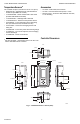

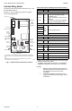

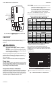


Table Of Contents

T775P SERIES 2000 CONTROLLER WIRING
62-0256–03 6
Controller Wiring Details
The wiring connection terminals are shown in Fig. 7 and
are described in Table 2.
See Fig. 8 – Fig. 12 beginning on page 7 for typical
T775P wiring applications.
Fig. 7. T775P Terminal and Feature Locations.
NOTES:
1. Relays 5–8 are assigned to the first T775S
Expansion Module, if connected. Relays 9–12
are assigned to the second T775S, if
connected.
2. If Expansion Modules are used, the pump
output is always the last relay output, 8 or 12
respectively.
M24375
SENSORS A, B, AND C (WHEN USED FOR TEMPERATURE SENSING)
USE THE TWO TT CONNECTIONS AND ARE POLARITY INSENSITIVE.
A SEPARATE EARTH GROUND IS REQUIRED FOR ANY POWER
SOURCE (24, 120, OR 240 VAC).
1
2
C
NO
NC
C
NO
NC
C
NC
NO
C
NC
NO
C
NO
NC
T
T
+
–
+
–
SENSOR A
SENSOR B
KNOCKOUT A
DIGITAL INPUT
POWER
120/240 VAC
OUTPUT
RELAY 2
KNOCKOUT D
POWER
24 VAC
OUTPUT
RELAY 1
KNOCKOUT C
KNOCKOUT E
1
OUTPUT
RELAY 3
KNOCKOUT B
T775 BUS
OUTPUT
RELAY 4
DIGITAL
OUTPUT
ALARM
2
T
T
SENSOR C
T
T
C
+
120
COM
240
Table 2. Description of Wiring Terminal Connections.
Connection Terminal Description
Sensors
Sensor A
Sensor B
Sensor C
T T
T T
T T
Temperature Sensor; polarity insensitive:
A - This sensor can be the controlled
temperature sensor
B - The control always uses this sensor for
Reset only
C - This sensor can be used for differential
and/or the controlled temperature sensor
Outputs
Relay 1
NO
COM
NC
120-240 Vac Relay Output
Relay 2
Relay 3
Relay 4
a
a
Relay 4 can be used for pump output. The pump output
is always the last relay output.
DO Digital Alarm Output
Input
DI + - Digital Input (dry contact)
Interconnect
T775 BUS
+
-
Terminal Connection to/from T775S
24 Vac Power
24V +
+
24 Vac Hot
Common
-
24 Vac Common
Ground
Earth Ground
b
b
A separate earth ground is required for all installations
regardless of the power source (24, 120, or 240 Vac).
120 or 240 Vac Power
120 Vac 120 120 Vac Power
Common COM Common
240 Vac 240 240 Vac Power