
Install Instructions

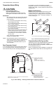

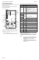

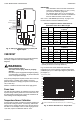


Table Of Contents

INTERFACE OVERVIEW T775P SERIES 2000 CONTROLLER
9 62-0256–03
INTERFACE OVERVIEW
The T775P controller uses an LCD panel and 6-button
keypad to provide status information and permit user input
of the programming, setup, and scheduling parameters.
The following figure describes the display areas of the
LCD and the keypad.
Fig. 14. LCD Display - Home Screen And Keypad.
Menu Area – On the home screen, the LCD displays the
configured relays and whether they are active. In
Program, Setup, or Schedule mode, the LCD displays the
current menu selection and its order within the menu
hierarchy.
Data Area – On the home screen, the LCD displays the
sensors and outputs status. In Setup or Program mode,
the LCD displays menu choices, parameter selections,
and data values.
Lock Icon – The icon indicates the MENU button is
locked and prevents access to the Setup and Program
menus.
NOTE: Pressing and holding the HOME and MENU
buttons simultaneously for five seconds locks/
unlocks the MENU button.
Alarm – If enabled in Setup, this label displays when a
limit is exceeded. The alarm label applies to either HIGH
LIMIT, LOW LIMIT, or DIFFERENTIAL alarms.
6-Button Keypad – The keypad is used to access the
menus and enter values (see “Using the LCD Panel
Interface”).
Using the LCD Panel Interface
The 6-button keypad is used to move through the menus
and enter or change parameter values.
Home Button
Pressing the HOME button at any time exits the current
Programming or Setup display screen and returns to the
home screen as shown in Fig. 14 and Fig. 15 on page 10.
Menu Button
1. Pressing the MENU button always displays the
Program menu. If you are in Setup mode, you exit
setup and return to the Program menu.
2. Pressing and holding the MENU button for five
seconds leaves the current screen and displays
the Setup menu.
Left and Right Arrow Buttons (W and X)
Use these buttons to move backward (W) and forward (X)
through the Program and Setup menus.
Up and Down Arrow Buttons (S and T)
Use these buttons to move your selection up and down
through a menu or list.
• When the desired item is highlighted, you press the X
arrow button to display that item’s content.
• When a value is displayed (e.g. 70°F), the up and
down arrows increase and decrease the value.
NOTE: Once you select an item from a list or enter a
value, pressing the W or X or HOME button
accepts your selection or value and stores it in
the controller’s memory.
Home Screen
In the normal run state, the LCD home screen displays
the current sensed temperatures, the active status of the
output relays (stages), and error and status codes.
Active relays are indicated by the small black square ()
just below the relay number. Fig. 15 on page 10 shows
the home screen with relays 1, 2, and 4 energized.
When using Reset, the Heat/Cool setpoint displays on the
home screen for the first four (4) staged outputs.
Pressing the W and X buttons from the home screen
cycles through the sensor and stage displays (Fig. 15).
NOTE: Only the first four (4) stages can be displayed.
DI ON
HOME
1 2 3 4 5 6 7 8 9 10 11 12
SENSORS
SUPPLY
A
180.5
OUTDOOR B
72.5
MENU AREA
home menu
F
o
F
o
DATA AREA
LOCK ICON
6 BUTTON KEYPAD
ALARM
RETURN C
100.5
F
o
A
LARM
M24393