
Install Instructions
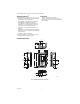
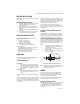
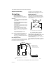
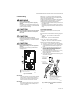
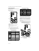
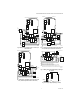
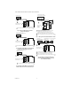
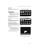
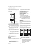
Table Of Contents

T775R SERIES 2000 ELECTRONIC STAND-ALONE CONTROLLER
62-0249—05 6
Controller Wiring Details
The wiring connection terminals are shown in Fig. 7 and
are described in Table 2.
See Figures 8 through 18 beginning on page 6 for typical
T775R wiring applications.
Fig. 7. T775R Terminal and Feature Locations.
NOTE: Refer to Table 1 on page 1 for the specific
configuration of sensors and outputs supported
by the model you are installing.
a
For Series 90 connections, you must insert a 340 Ohm
resistor across terminals R and W (Refer to Fig. 17 on
page 8). The resistor is included with the controller.
b
A separate earth ground is required for all installations
regardless of the power source (24, 120, or 240 Vac).
WIRING APPLICATION EXAMPLES
Figures 8 through 18 illustrate typical controller wiring for
various applications.
NOTE: For wiring examples of Series 90, M9184 or
M9185 Modutrol Motors, refer to the T775A/B/M
Series 2000 Electronic Stand-alone Controllers
Installation Instructions (form 62-0254).
Fig. 8. Wiring for Two-Stage Control – 24 Vac Input
and 24 Vac Load.
Table 2. Description of Wiring
Terminal Connections.
Connection Terminal Label Description
Sensors
Sensor A T T Temperature Sensor;
polarity insensitive
Sensor B
Outputs
Relay 1
Relay 2
Relay 3
Relay 4
NO
COM
NC
120-240 Vac Relay
Output
Mod 1 + - (Vdc or mA)
W R B (Series 90)
a
Modulating Output
Mod 2
Input
DI + - Digital Input (dry
contact)
C
NO
NC
C
NO
NC
C
NC
NO
C
NC
NO
T
T
T
T
B
R
W
+
–
+
–
B
R
W
+
–
SENSOR A
SENSOR B
MOD 2
MOD 1
KNOCKOUT A
DIGITAL
INPUT
POWER
120/240 VAC
OUTPUT
RELAY 2
KNOCKOUT D
POWER
24 VAC
OUTPUT
RELAY 1
KNOCKOUT C
KNOCKOUT E
SENSORS A AND B USE THE TWO TT CONNECTIONS AND ARE
POLARITY INSENSITIVE.
FOR MOD 1 AND MOD 2 CURRENT (mA) OR VOLTAGE (VDC) OUTPUT,
USE SIGNAL (+) & COMMON (-).
FOR MOD 1 AND MOD 2 SERIES 90 OUTPUT, USE W, R, & B.
A SEPARATE EARTH GROUND IS REQUIRED FOR ANY POWER
SOURCE (24, 120, OR 240 VAC).
1
2
1
2
M24284
OUTPUT
RELAY 3
KNOCKOUT B
OUTPUT
RELAY 4
3
3
C
+
120
COM
240
24 Vac Power
24V + + 24 Vac Hot
Common C 24 Vac Common
Ground
Earth Ground
b
120 or 240 Vac Power
120 Vac 120 120 Vac Power
Common COM Common
240 Vac 240 240 Vac Power
Table 2. Description of Wiring
Terminal Connections. (Continued)
Connection Terminal Label Description
L1
(HOT)
L2
24 VAC
COM
NO
COM
NO
M24285A
LOAD 2
LOAD 1
C
NO
NC
C
NO
NC
C
+
SENSOR A
SENSOR B
T
T
T
T