
Thermostat User Manual


T874 MULTISTAGE THERMOSTATS AND Q674 SUBBASES
60-2485—8 12
Most heat pump systems should cycle 2-1/2 to 3 times per hour.
4. Hang the upper edge of the thermostat cover on top of
the thermostat base and swing the cover downward
until it engages with the cover clip.
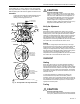
Fig. 11. Adjustable heat anticipator scales.
Temperature Setting
Move the heating and cooling levers to the desired comfort
positions. See Fig. 12. On some models with two stages of
heating or cooling, the same lever controls both stages. The
minimum differential between heating and cooling setpoints is
4°F (2°C) (5°F [3°C]) on T874W.
If model has optional screws to lock temperature control
levers, loosen these screws before making temperature
adjustment; tighten the screws when levers are set at desired
position.
Fig. 12. Internal view of T874W (three stages of
heating, two stages of cooling).
Subbase Setting
The subbase switching positions control the system operation
as described below.
SYSTEM SWITCH (see subbase for positions):
OFF—both the heating and cooling systems are off. If the
fan switch is at the AUTO position, the cooling fan is
also off.
HEAT—heating system is automatically controlled by the
thermostat. Cooling system is off.
AUTO—thermostat automatically changes between heat-
ing and cooling system operation, depending on the
indoor temperature.
COOL—cooling system is automatically controlled by the
thermostat. Heating system is off.
EM.HT.—emergency heat relay is automatically controlled
by the thermostat. Cooling system is off. Compressor is
de-energized.
SUPL.HT.—supplemental heat relay is energized. Cooling
system is off. Compressor is de-energized.
WOOD—heating system is operating with only the wood-
burning stage.
OIL—heating system is operating with only the oil-burning
stage.
WOOD/OIL—wood and oil stages operate sequentially;
first the WOOD stage operates, then the OIL stage
operates if the WOOD stage cannot handle the load.
EVAP—controls cooling system by water evaporation; see
equipment instructions for further information.
OVERRIDE—night setback is disabled.
ON—heating system is controlled by the thermostat. EM.
HT. or SUPL. HT. relay is not energized.
FAN SWITCH positions control fan operation as follows:
ON or CONT.—fan operates continuously.
AUTO—fan operates as controlled by the thermostat in
heat pump systems or conventional cooling mode; fan
operates as controlled by the plenum switch in conven-
tional heating mode.
LO—fan operates constantly at low speed.
MED—fan operates constantly at medium speed.
HI—fan operates constantly at high speed.
To move the subbase switches to the desired control
positions, use thumb and index finger to slide the lever. The
lever must stop over desired function indicator position for
proper circuit operation.
Spring return momentary position switching feature is
available on selected subbase models. On these models, the
fan switch is positioned to the right of the system switch. By
moving the fan switch to the far right and releasing it, the ON
position circuit makes. The lever springs back on release. This
position is not marked on the subbase.
Setting the Adjustable Differential
The adjustable interstage differential feature, on a selected
T874D model only, can be identified by the scale and tension
screw near the heating and cooling mercury switches. See
Fig. 13. On this model, the number of degrees between the
making of the first and second stage mercury bulbs is
adjustable. This feature is especially useful if the first stage
controls the comfort temperature, and the second stage
controls the energy savings temperature. Timers, such as the
S6005, for insertion between the first and second stage
control points must be ordered separately.
Each mark on the scale represents 1°F (0.6°C) The
differential is factory set at 2°F (1°C) the differential can be set
as high as 12°F (7°C) To set the adjustable interstage
differential, loosen the tension screw. See Fig. 13. Slide the
adjustable scale to align with the number of degrees desired
between stages. Use the lower edge of the tension screw
bracket as a guide for alignment. In heating, slide the lever
wider apart for a larger differential, or closer together for a
1.2
.4
.6
.3
.2
.15
.12
.10
.8
1.2
.4
.6
.3
.2
.15
.12
.8
.5
MOVE INDICATOR TO
MATCH CURRENT RATING
OF PRIMARY CONTROL
STAGE ONE
ANTICIPATOR
HEATING
CONTROL
STAGE TWO
ANTICIPATOR
HEATING CONTROL
M506
9
STAGE 1
HEATING
STAGE 3
HEATING
STAGE 2
HEATING
HEATING
LEVER
COOLING
LEVER
STAGE 1
COOLIN
G
STAGE 2
COOLING
CAPTIVE
MOUNTING
SCREWS (2)
M7625