
Thermostat User Manual


T874 MULTISTAGE THERMOSTATS AND Q674 SUBBASES
60-2485—8 22
CAUTION
Equipment Damage Hazard.
Due to calibration techniques used for T874
Thermostats with outdoor reset, the C815A Thermistor
must be wired into the system at all times. Failure to
do so will result in serious degradation of performance.
Service and Replacement of C815A Outdoor
Thermistor
To check and verify thermistor operation, perform the
following steps:
1. Disconnect wire from T terminal on subbase.
2. Measure resistance with ohmmeter across the T sub-
base wire and X subbase terminal.
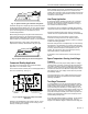
3. Take outdoor temperature measurement at thermistor
location and find correct thermistor resistance on the
chart in Fig. 29.
4. Compare resistance on the chart with measured resis-
tance. Replace C815A if resistance varies more than 15
percent. Contact installing dealer for packaged replace-
ment outdoor thermistor.
Fig. 29. Thermistor resistance chart.
Features
Two of the features of the T874/Q674 include LED indicators
and restricted setpoint.
LED Indicators
The light-emitting diodes (LED) indicators on the subbase
light on command when something specific happens in the
system. See Fig. 30.
Up to four different LEDs are available. The thermostat has a
clear lens window for viewing each LED. On TRADELINE
models, a small insert is used so the LED function desired can
be selected. This must be done during installation.
A blank insert is factory-installed in some T874 models. To
remove it, push both temperature setting levers to the far ends
of the thermostat. Use index fingernail to gently pull out the
scaleplate a fraction of an inch. Turn thermostat upside-down,
and the blank insert falls out.
A strip of four inserts is included with TRADELINE T874. Drop
a strip into the recessed area behind the scaleplate so
selected LEDs show. Make sure insert is completely seated in
recessed area. Let scaleplate pop back; then set levers to
desired position.
• FILTER LED lights when the filter is clogged and needs
replacement.
• CHECK LED lights when something needs to be checked
or done to maintain efficient operation of system. See
heating system instructions for CHECK LED meaning.
• EM. HT. LED lights when the emergency heat is operating.
• SUPL. HT. LED lights when the supplemental heat is
operating.
• LOCKOUT LED lights when the system is shut down and
needs maintenance.
• AUXILIARY HEAT LED lights when the auxiliary heat is
operating.
• SERVICE or MALFUNCTION LED can have several
meanings. Consult heating system instructions.
LEDs cannot be replaced or added in the field.
Fig. 30. T874/Q674 LED location.
Restricted Setpoint (DoD)
The Department of Defense (DoD) models are equipped with
a restricted setpoint feature for fuel efficiency.
Fixed stops are factory-set so setpoint levers cannot be set
above 72°F (22°C) on heating, or below 78°F (26°C) on cooling.
Applications
The T874/Q674 can be applied to standard residential
systems for automatic or manual changeover, to commercial
rooftop applications, or to heat pump applications.
Changeover on Standard Residential
Systems
In a standard residential heating-cooling circuit, changeover
between heating and cooling can be done either automatically
or manually.
Automatic changeover is done by an AUTO position on the
subbase system switch. See Fig. 31. When the switch is in the
AUTO position, the thermostat automatically changes between
heat and cool modes, depending on the indoor temperature.
THERMISTOR RESISTANCE (ohms)
C815A THERMISTOR RESISTANCE
R = 400 ohms ± 10% AT 77°F (25°C)
4600
4400
4200
4000
3800
3600
3400
3200
3000
2800
2600
2400
2200
2000
1800
1600
1400
1200
1000
800
600
400
200
0
-20 0 20 40 60 80 100 120 14
0
TEMPERATURE OF THERMISTOR (°F)
M1590A
80
50 60 70 80
COOL
EM.
HEAT
FILTER SERV.
AUX
HEAT
M583
0
LEDS