
Install Instructions
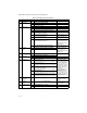


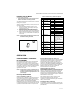


Table Of Contents

TB6575/TB8575 SUITEPRO™ DIGITAL FAN COIL THERMOSTATS
13 62-0278—13
8.5 Fan Speed at motor
start up
0 Provide full power when fan motor starts –
always starts in high fan speed (Default)
High speed start up
ensures that there is
enough torque to start the
motor and eliminates and
motor locking.
1 Disable – fan will start at speed that is needed as
defined by VersaSpeed
9 Number of Fan
Speeds
1 Single Speed Fan Low speed only
2 2 Speed Fan Hi and Low speed fans only
3 3 Speed Fan (Default) Hi, Med, and Low speed fan
9.5 Fan Control Type 0 Constant and Auto (Default) When fan is in Auto, the fan
ramping algorithm,
Veraspeed, is used
1 Auto only
10 Control Method for
4-Pipe Auto
Changeover
1 Single Setpoint (Default) Uses switching differential
to change between heating
and cooling and controls to
a single setpoint (Only
displayed for system types
5 or 7)
2 Heat and Cool Setpoints (2 setpoint method) Uses a deadband of no
control and controls to a
heat or cool setpoint. (Only
displayed for system types
5 or 7)
10.5 Deadband for Heat/
Cool Setpoints
2 to 9 Range is 2 to 9. Default is 3. Deadband = minimum
distance between heating and cooling setpoints.
Available when Heat and
Cool Setpoints are chosen
for the control method for 4-
pipe Auto (IS 10)
Switching
Differential for
Single Setpoint
2 to 6 Range is 2 to 6. Default is 3. Heat switching point =
setpoint - switching differential. Cool switching point
= setpoint + switching differential.
Available when Single
Setpoint is chosen for the
control method for 4-pipe
Auto (IS 10)
11 CPH Value for Heat 1 to 12 Range is 1 to 12. Default is 4. The number selected
indicates the maximum
times Heating is cycled on
per hour (CPH).
12 CPH Value for Cool 1 to 6 Range is 1 to 6. Default is 3. The number selected
indicates the maximum
times Cooling is cycled on
per hour (CPH).
13 CPH for Auxiliary
Electrical Heater
1 to 12 Range is 1 to 12. Default is 6. The number selected
indicates the maximum
times Auxiliary Heating is
cycled on per hour (CPH).
14 Display
Temperature
Adjustment
-4 to 4 Range is -4°F to +4°F; Default is 0°F.
15 Temperature
Display Mode
0 Display Room Temperature
1 Display Setpoint
2 Display Temperature and Setpoint; Default.
16 Setpoint Range
Stop for Heating
50 to
90
Range is 50°F to 90°F. Default is 90°F.
17 Setpoint Range
Stop for Cooling
50 to
90
Range is 50°F to 90°F. Default is 50°F.
18 Keypad Lockout 0 All keys are available (Default)
1 The System button (Heat/Cool) is locked out
2 Both the System and Fan buttons are locked out.
3 All buttons are locked out (System, Fan, Up Arrow,
and Down Arrow). The LCD displays LOCKED.
Table 4. Installer Setup (IS) Codes and Options. (Continued)
IS
Code Code Description
Option
Value
Option Description (Default value shown in
Bold) Notes