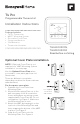
T4 Pro Programmable Thermostat Installation Instructions Package Includes: • T4 Pro Thermostat • UWP™ Mounting System • Decorative Cover Plate • Screws and Anchors • 2 AA Batteries • Thermostat Literature TH4110U2005, TH4210U2002 Read before installing Optional Cover Plate installation NOTE: If Optional Cover Plate is not required, see “UWP Mounting System installation” on next page. 1 Use the Optional Cover Plate when you need to cover paint gap from old thermostat.
For the rectangular cover plate: 1. Mount the Cover Plate on the wall using any of the 6 screw holes. Insert and tighten the mounting screws supplied with the Cover Plate. Do not overtighten. See Figure 1. Make sure the Cover Plate is level. Attach the UWP by hanging it on the top hook of the Cover Plate and then snapping the bottom of the UWP in place. See Figure 2. 2. If there are no existing wall anchors: a. Position the Cover Plate on wall. Level and mark hole positions. See Figure 1. b.
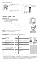
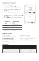
Power options S S Y Y2 G C U U A L/A O/B AUX W2 E W K R Rc Insert R and C wires into designated terminals for primary AC power (C terminal is optional if batteries are installed, but it is recommended). Remove wires by depressing the terminal tabs. Insert AA batteries for primary or backup power. Setting Slider Tabs UWP Mounting System Set R Slider Tab. • Use built-in jumper (R Slider Tab) to differentiate between one or two transformer systems.
Wiring conventional systems: forced air and hydronics 1H/1C System (1 transformer) R Power [1] Rc [R+Rc joined by Slider Tab] [2] Y Compressor contactor C 24VAC common [3] W Heat G Fan 1H/1C System (2 transformers) R Power (heating transformer) [1] Rc Power (cooling transformer) [1] Y Compressor contactor C 24VAC common [3, 4] W Heat G Fan Heat-only System R Power [1] Rc [R+Rc joined by Slider Tab] [2] C 24VAC common [3] W Heat Heat-only System with Fan R Power [1] Rc [R+Rc joined by Slider Tab] [2] C 24
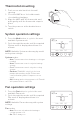
Thermostat mounting 1. Push excess wire back into the wall opening. 2. Close the UWP door. It should remain closed without bulging. 3. Align the UWP with the thermostat, and push gently until the thermostat snaps in place. 4. Turn the power on at the breaker box or switch. System operation settings 1 Press the Mode button to cycle to the next available System mode. 2 Cycle through the modes until the required System mode is displayed and leave it to activate.
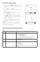
Installer setup (ISU) 1 Press and hold CENTER and buttons for approximately 3 seconds to enter advanced menu. 2 Press Select to enter ISU. 3 Press Select to cycle through menu setup options. 4 Press or to change values or select from available options. 5 Press Select and confirm your settings or press Back to ignore changes and return to ISU menu screen to continue editing another setup option. 6 To finish setup process and save your setting, press Home and return to Home screen.
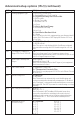
Advanced setup options (ISU) (continued) # ISU 205 ISU Name Heating Equipment Type ISU Options (factory default in bold) Conventional Forced Air Heat: 1 = Standard Efficiency Gas Forced Air 2 = High Efficiency Gas Forced Air 3 = Oil Forced Air 4 = Electric Forced Air 5 = Hot Water Fan Coil Heat Pump: 7 = Air to Air Heat Pump 8 = Geothermal Heat Pump Radiant Heat: 9 = Hot Water Radiant Heat 12 = Steam Note: This option selects the equipment type your thermostat will control.
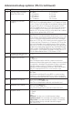
Advanced setup options (ISU) (continued) # ISU ISU Name ISU Options (factory default in bold) 350 Upstage Timer for Backup Heat (TH4210U only) 0 = Off 1 = 30 minutes 2 = 45 minutes 3 = 60 minutes 4 = 75 minutes 365 Compressor Cycle Rate (Stage 1) 370 Heating Cycle Rate (Stage 1) 375 387 Heating Cycle Rate Auxiliary Heat (TH4210U only) Compressor Protection 1-6 Note: This ISU is only displayed when Cool /Compressor Stage is set to 1 stage.
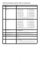
Advanced setup options (ISU) (continued) # ISU 702 ISU Name Number of Air Filters 711 Air Filter 1 Replacement Reminder 712 Air Filter 2 Replacement Reminder 1400 Backlighting 1401 Backlight brightness 1410 1415 Clock Format Daylight Saving Time 1420 Temperature Display Offset ISU Options (factory default in bold) 0-2 Note: This ISU refers to the number of air filters in the system.
Installer system test To perform a System Test: 1 Press and hold CENTER and buttons for approximately 3 seconds to enter advanced menu. 2 Use to go to TEST. Press Select to enter System Test. 3 Use to change between Heat, Cool, Fan, Em. Heat (TH4210U only), or Ver (thermostat version information). Press Select. 4 Press to turn heat, cool, or fan on. Press to turn them off. 5 Use the Home button to exit the System Test. System test Heat Cool Fan Em.
Troubleshooting If you have difficulty with your thermostat, please try the following suggestions. Most problems can be corrected quickly and easily. Display is blank • • • • Heating or cooling system does not respond • Press Mode button to set system Heat (see page 5). Make sure the desired temperature is set higher than the inside temperature. • Press Mode button to set system Cool (see page 5). Make sure the desired temperature is set lower than the inside temperature.
CAUTION: ELECTRICAL HAZARD Can cause electrical shock or equipment damage. Disconnect power before beginning installation. CAUTION: EQUIPMENT DAMAGE HAZARD Compressor protection is bypassed during testing. To prevent equipment damage, avoid cycling the compressor quickly. CAUTION: MERCURY NOTICE If this product is replacing a control that contains mercury in a sealed tube, do not place the old control in the trash.
T4 Pro Thermostat programmable Notice d’installation La boîte comprend : • Thermostat T4 Pro • Système de montage UWP • Plaque de couvercle décorative • Vis et chevilles • 2 piles AA • Documentation du thermostat TH4110U2005, TH4210U2002 Lire avant l’installation. Installation de la plaque de couvercle en option REMARQUE : Si la plaque de recouvrement en option n’est pas requise, consultez la section « Installation du système de montage UWP » à la page suivante.
Installation du système de montage UWP Plaque de recouvrement rectangulaire : 1. Posez la plaque de recouvrement au mur à l’aide des 6 trous de vis. Insérez et serrez les vis fournies avec le couvercle de recouvrement. Ne serrez pas excessivement. Voir la figure 1. Assurez-vous que la plaque de recouvrement est de niveau. Fixez l’UWP en l’accrochant au crochet supérieur de la plaque de recouvrement, puis en l’enclenchant en place par le bas. Voir la figure 2. 2.
Options d’alimentation S S Y Y2 G C U U L/A A O/B AUX W2 E W K R Rc Insérer les fils R et C dans les bornes désignées pour l’alimentation principale en courant alternatif (la borne C est facultative si les piles sont installées, mais elle est recommandée). Retirer les fils en appuyant sur les languettes de la borne. Insérer les piles AA pour assurer l’alimentation principale ou de secours. Réglages des curseurs Régler le curseur R.
Câblage des systèmes conventionnels : air forcé et hydronique Système à 1 étage de chauffage/1 étage de refroidissement (1 transformateur) R Alimentation [1] Rc [R+Rc liés par le curseur] [2] Y Contacteur du compresseur C Borne commune 24 V c.a. [3] W Chauffage G Ventilateur Système à 1 étage de chauffage/1 étage de refroidissement (2 transformateurs) R Alimentation (transformateur de chauffage) [1] Rc Alimentation (transformateur de refroidissement) [1] Y Contacteur du compresseur C Borne commune 24 V c.
Montage du thermostat 1. Repousser le fil en excès dans l’ouverture du mur. 2. Fermer le couvercle du UWP. Elle doit rester fermée sans renflement. 3. Aligner l’UWP sur le thermostat, et appuyer doucement jusqu’à ce que le thermostat s’enclenche en place. 4. Mettre l’alimentation en marche au niveau du disjoncteur du circuit ou de l’interrupteur. Réglages pour le fonctionnement du système 1 Appuyer sur le bouton Mode pour passer au prochain mode de système disponible.
Configuration de l’installateur (ISU) 1 Appuyer sur CENTER (Centre) et sur les boutons pendant 3 secondes environ pour accéder au menu des réglages avancés. 2 Appuyer sur Select (Sélectionner) pour accéder à ISU (Configuration de l’installateur). 3 Appuyer sur Select (Sélectionner) pour faire défiler les options de configuration du menu. 4 Appuyer sur ou pour changer les valeurs ou faire une sélection à partir des options disponibles.
Options de configuration avancées (ISU) (suite) N° ISU Nom ISU Options ISU (réglage d’usine en gras) Chauffage à air pulsé conventionnel : 1 = Air pulsé à gaz efficacité standard 2 = Air pulsé à gaz haute efficacité 3 = Air pulsé au mazout 4 = Air pulsé électrique 5 = Ventiloconvecteur à eau chaude 205 218 220 221 230 300 303 340 350 Type d’équipement de chauffage Thermopompe : 7 = Thermopompe air-air 8 = Thermopompe géothermique Chauffage rayonnant : 9 = Chauffage rayonnant à eau chaude 12 =
Options de configuration avancées (ISU) (suite) N° ISU Nom ISU 365 Cycle du compresseur (étage 1) 370 Cycle de chauffage (étage 1) 375 Nombre de cycle de chauffage du chauffage auxiliaire 387 425 430 431 435 Options ISU (réglage d’usine en gras) 1-6 Remarque : Cette configuration installateur (ISU) ne s’affiche que lorsque la phase de refroidissement ou la phase du compresseur est réglée à la phase 1.
Options de configuration avancées (ISU) (suite) N° ISU Nom ISU 702 Nombre de filtres à air 711 Rappel de remplacement du filtre à air 1 712 Rappel de remplacement du filtre à air 2 1400 Rétroéclairage 1401 Luminosité du rétroéclairage 1410 Format de l’horloge 1415 Heure d’été/hiver 1420 Décalage d’affichage de température Options ISU (réglage d’usine en gras) 0-2 Remarque : Cette configuration installateur indique le nombre de filtres à air du système.
Test du système de l’installateur Pour réaliser un test du système : 1 Appuyer sur CENTER (Centre) et sur les boutons pendant 3 secondes environ pour accéder au menu des réglages avancés. 2 Utiliser pour passer à TEST. Appuyer sur Select (Sélectionner) pour accéder au test du système. 3 Appuyez sur pour sélectionner les modes « Heat » (chauffage), « Cool » (climatisation), « Fan » (ventilateur) et « Em » (urgence).
Dépannage En cas de difficultés avec le thermostat, essayez les suggestions suivantes. La plupart des problèmes peuvent être réglés rapidement et facilement. Rien n’apparaît • Vérifiez le disjoncteur et réinitialisez-le si nécessaire. à l’écran • Assurez-vous que l’interrupteur de marche-arrêt du système de chauffage et de refroidissement est sur marche. • Assurez-vous que la porte de l’appareil de chauffage est bien fermée.
MISE EN GARDE: RISQUE DE CHOC ÉLECTRIQUE Peut provoquer des chocs électriques ou endommager le matériel. Couper l’alimentation électrique avant d’effectuer le raccordement. MISE EN GARDE: RISQUE DE DOMMAGES DE L’ÉQUIPEMENT La protection du compresseur est annulée durant le test. Pour éviter d’endommager l’équipement, éviter d’actionner le compresseur trop rapidement.
T4 Pro Termostato programable Instrucciones para la instalación El paquete incluye: • Termostato T4 Pro • Sistema de montaje UWP™ • Placa de cubierta decorativa • Tornillos y tarugos • 2 baterías AA • Material de lectura sobre el termostato TH4110U2005, TH4210U2002 Leer antes de instalar. Instalación de la placa de cubierta opcional NOTA: Si no es necesaria la placa de cubierta opcional, consulte la “Instalación de sistema de montaje UWP” en la página siguiente.
Instalación del sistema de montaje con UWP Instalación de la placa de cubierta rectangular: 1. Monte la placa de cubierta en la pared con uno de los 6 orificios para tornillos. Inserte y ajuste los tornillos de montaje suministrados con la placa de cubierta. No ajuste demasiado. Consulte la figura 1. Asegúrese de que la placa de cubierta esté nivelada. Fije el UWP colgándolo en el gancho superior de la placa de cubierta y luego enganche la parte inferior del UWP. Consulte la figura 2. 2.
Opciones de suministro eléctrico S S Y Y2 G C U U L/A A O/B AUX W2 E W K R Rc Inserte los cables R y C en los terminales designados para el suministro primario de de energía de CA (el terminal C es opcional si se instalan baterías, pero se recomienda). Retire los cables presionando las lengüetas terminales. Inserte las baterías AA para suministro de energía primaria o de reserva. Configuración de las lengüetas de los controles deslizantes Configure la lengüeta del control deslizante R.
Cableado de sistemas convencionales: aire forzado e hidrónico Sistema de 1 etapa de calefacción/1 etapa de refrigeración (1 transformador) R Alimentación [1] Rc [R+Rc unidos por la lengüeta del control deslizante] [2] Y Contactor del compresor C Común de 24 V CA [3] W Calefacción G Ventilador Sistema de 1 etapa de calefacción/1 etapa de refrigeración (2 transformadores) R Alimentación (transformador de calefacción) [1] Rc Alimentación (transformador de refrigeración) [1] Y Contactor del compresor C Común d
Montaje del termostato 1. Introduzca el excedente de cable en la abertura de la pared. 2. Cierre la tapa de la placa de la UWP. Debe permanecer cerrada sin quedar protuberante. 3. Alinee la UWP con el termostato y presione suavemente hasta que el termostato calce en su lugar. 4. Conecte el suministro de electricidad en la caja de interruptores de circuito o en el interruptor. Configuraciones del sistema operativo 1 Presione el botón Mode (modo) para pasar al siguiente modo disponible en el sistema.
Configuración por el instalador (ISU) 1 Presione y sostenga CENTER (centro) y los botones durante aproximadamente 3 segundos para ingresar al menú avanzado. 2 Presione Select (seleccionar) para ingresar al ISU. 3 Presione Select (seleccionar) para avanzar a través de las opciones del menú de configuración. 4 Presione o para cambiar los valores o seleccionar las opciones disponibles.
Opciones avanzadas de configuración (ISU) (continuado) N.
Opciones avanzadas de configuración (ISU) (continuado) N.
Opciones avanzadas de configuración (ISU) (continuado) N.
Prueba del sistema por parte del instalador Para realizar una prueba del sistema: 1 Presione y sostenga CENTER (centro) y los botones durante aproximadamente 3 segundos para ingresar al menú avanzado. 2 Use para ir a TEST (prueba). Presione Select (seleccionar) para iniciar la prueba del sistema. 3 Utilice para alternar entre Heat (Calefacción), Cool (Refrigeración), Fan (Ventilador), Em. Heat (Calefacción de emergencia) (únicamente TH4210U) o Ver (Información de versión del termostato).
Localización y solución de problemas Si tiene dificultades con el termostato, intente seguir las sugerencias que se indican a continuación. La mayoría de los problemas pueden solucionarse de manera fácil y rápida. La pantalla está • Revise el interruptor de circuito y, si es necesario, reinícielo. en blanco • Asegúrese de que el interruptor de suministro de energía del sistema de calefacción y refrigeración esté encendido. • Asegúrese de que la puerta del sistema de calefacción esté bien cerrada.
PRECAUCIÓN: PELIGRO DE ELECTROCUCIÓN Puede causar descargas eléctricas o daños al equipo. Desconecte el suministro eléctrico antes de comenzar la instalación. PRECAUCIÓN: RIESGOS DE DAÑOS AL EQUIPO Se evita la protección del compresor durante la prueba. Para prevenir daños al equipo, evite encender y apagar rápidamente el compresor.