
VisionPRO 8000 Spec Sheet 2017


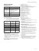
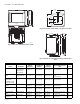
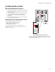
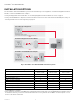


Table Of Contents
- Application
- Features
- Contents
- Specifications
- System Installation
- Installation Options
- Guidelines for Installing RedLINK Devices
- Installing Equipment Interface Module (if used)
- Wiring 24 Vac Common
- Selecting Discharge and Return Air Temperature Sensor Mounting Locations
- Installing Discharge and Return Air Temperature Sensors
- Selecting Thermostat Location
- Installing Wallplate
- Installing VisionPRO® 8000 with RedLINK™
- Wiring the Thermostat
- Remove Coin Cell Battery Tab
- Mounting Thermostat on Wallplate
- Power Optional RedLINK™ Accessories
- Performing Initial Setup
- Installer Tests
- Operation
- Setting the Time/Date
- Setting the Fan
- Setting System Mode
- Adjusting Program Schedules
- Overriding Schedules: Residential Use
- Overriding Schedules: Commercial Use
- Viewing Equipment Status
- Setting Vacation Hold: Residential Use
- Setting Holiday/Event Schedules: Commercial Use
- Setting Custom Events: Commercial Use
- Setting Holiday Schedule: Commercial Use
- Setting Holiday Override: Commercial Use
- Initiating Occupancy Mode: Commercial Use
- Remote Setback: Commercial Use
- Adjusting Humidification Settings
- Adjusting Dehumidification Settings: Residential Use
- Adjusting Dehumidification Settings: Commercial Use
- Adjusting Ventilation Settings
- Ventilation Options
- Setting Preferences
- Cleaning the Thermostat Screen
- Adjusting Security Settings
- Viewing Dealer Information
- Advanced Features
- Installer Options
- Using the Temperature Display
- Using the Humidity Display
- Universal Outputs (U1, U2, U3)
- Universal Inputs (S1, S2, S3, S4)
- Data Logs
- Dry Contact Alerts
- Set Up the Dry Contact Alerts
- Staging Control
- Heat Pump and Backup Heat Operation
- Indoor Air Quality (IAQ) Control
- IAQ Reminders
- Customizable Reminders
- MicroSD card
- Commercial Features
- Overriding Schedules: Commercial Use
- Setting Holiday/Event Schedules: Commercial Use
- Setting Custom Events: Commercial Use
- Setting Holiday Schedule: Commercial Use
- Setting Holiday Override: Commercial Use
- Initiating Occupancy Mode: Commercial Use
- Ramp Rates (Commercial Use)
- Remote Setback (Commercial Use)
- Economizer and Time of Day (TOD) Operation
- Pre-Occupancy Purge
- Battery Replacement
- Optional Accessories
- Portable Comfort Control
- Remote Indoor Sensors
- Replacing a Thermostat
- Replacing an Equipment Interface Module
- Wiring
- Zoning
- Troubleshooting
- Regulatory Information

VISIONPRO
®
8000 WITH REDLINK™
9 68-0312—05
Guidelines for Installing RedLINK
Devices
— When installing more than one Thermostat and
Equipment Interface Module, mount the Equipment
Interface Modules at least 2 feet apart for best RedLINK
performance. No minimum distance is required
between the Thermostats if the Thermostat is linked to
an Equipment Interface Module.
— When the Thermostat is wired directly to the equipment
(No Equipment Interface Module and No TrueZONE
Wireless Adapter), mount the Thermostats at least 2 feet
apart for best RedLINK performance.
— To determine if a RedLINK device will communicate
properly in the installed location, during the connection
process, press and quickly release the connect button
on the RedLINK device at the desired mounting location
.
If the RedLINK device connects, then it will work reliably
during normal operation. If the RedLINK device does
NOT connect, try a new location. During the connection
process, the signal is sent at low power and during
normal operation the signal is sent at high power.
— To connect a RedLINK device, make sure to press and
quickly release the connect button on the RedLINK
device. Press and holding the connect button down too
long will not allow the device to connect.
— If you link the Thermostat to the TrueZONE Wireless
Adapter, you will NOT be able to do the following: control
humidification, dehumidification or ventilation, setup a
program schedule remotely from a computer, smart
phone or tablet, work with the Wireless Indoor Sensor,
Entry / Exit Remote or the Vent and Filter Boost Remote.
To use these features, wire the Thermostat directly to the
zone panel or use an Equipment Interface Module.
— If you are using a RedLINK device from a previous
installation, you must reset the device first before you
re-connect it to the new Thermostat/Equipment
Interface Module. See page 119 for more information.
Installing Equipment Interface
Module (if used)
If no Equipment Interface Module is used, skip to
“Selecting Thermostat Location” beginning on page 12.
NOTE: If an EIM is mounted inside a metal cabinet, such
as a commercial rooftop unit, it is recommended
to use a THM4000R1000 Wireless Adapter for
extended wireless range. Mount the Wireless
Adapter outside the metal cabinet and connect to
the ABCD terminals at the EIM. The Wireless
Adapter functions as a remote antenna for the
EIM. After it is wired to the EIM, it automatically
takes over as the antenna for RedLINK communi-
cation. For best RedLINK performance, avoid
mounting the Wireless Adapter above the roof
deck or outside the exterior walls.
NOTE: If you install more than one thermostat and EIM,
the EIMs must be at least 2 feet apart for best
RedLINK performance.
CAUTION
Electrical Hazard.
Can cause electrical shock or equipment damage.
Disconnect power before wiring.
The Equipment Interface Module (EIM) can be mounted
vertically on the HVAC equipment or on a wall in the
equipment room.
1. Mount the EIM near the HVAC equipment, or on the
equipment itself. Use screws & anchors as appropri-
ate for the mounting surface.
2. To wire the EIM, strip 1/4” insulation, then insert
wires (see Fig. 7). For wiring diagrams, see “Wiring”
beginning on page 121.
Fig. 6. THM4000R1000 Wireless Adapter wired to the
EIM.
Fig. 7.
NOTE: Link EIM to thermostat BEFORE linking any
RedLINK accessories. See “Linking RedLINK
Accessories” on page 16.
3. If you are installing discharge and return air sensors,
see “Selecting Discharge and Return Air Temperature
Sensor Mounting Locations” beginning on page 10).
Wiring 24 Vac Common
• Single-Transformer System—Connect the common side
of the transformer to the C screw terminal of the EIM.
Leave the metal jumper wires in place between R, RC,
and RH.
• Two-Transformer System—Connect the common side of
the cooling transformer to the C screw terminal of the
EIM. Remove the metal jumper wire between RC and RH.
Connect the hot side of heating transformer to RH and
leave the jumper wire between R and RC and connect
the hot side of cooling transformer to R or RC.
EIM
A
B
C
D
WIRELESS
ADAPTER
CONNECT
POWER
THM4000R
CONNECTED
WIRELESS SETUP
C
O
NN
E
C
T
CONNECTED
MCR34049A
R
C
Y
Y2
G
W
O/B
W2
AUX1
W3
AUX2
A
L/A