
VisionPRO 8000 Spec Sheet 2017
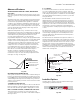
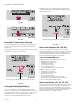

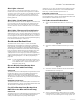
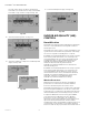
Table Of Contents
- Application
- Features
- Contents
- Specifications
- System Installation
- Installation Options
- Guidelines for Installing RedLINK Devices
- Installing Equipment Interface Module (if used)
- Wiring 24 Vac Common
- Selecting Discharge and Return Air Temperature Sensor Mounting Locations
- Installing Discharge and Return Air Temperature Sensors
- Selecting Thermostat Location
- Installing Wallplate
- Installing VisionPRO® 8000 with RedLINK™
- Wiring the Thermostat
- Remove Coin Cell Battery Tab
- Mounting Thermostat on Wallplate
- Power Optional RedLINK™ Accessories
- Performing Initial Setup
- Installer Tests
- Operation
- Setting the Time/Date
- Setting the Fan
- Setting System Mode
- Adjusting Program Schedules
- Overriding Schedules: Residential Use
- Overriding Schedules: Commercial Use
- Viewing Equipment Status
- Setting Vacation Hold: Residential Use
- Setting Holiday/Event Schedules: Commercial Use
- Setting Custom Events: Commercial Use
- Setting Holiday Schedule: Commercial Use
- Setting Holiday Override: Commercial Use
- Initiating Occupancy Mode: Commercial Use
- Remote Setback: Commercial Use
- Adjusting Humidification Settings
- Adjusting Dehumidification Settings: Residential Use
- Adjusting Dehumidification Settings: Commercial Use
- Adjusting Ventilation Settings
- Ventilation Options
- Setting Preferences
- Cleaning the Thermostat Screen
- Adjusting Security Settings
- Viewing Dealer Information
- Advanced Features
- Installer Options
- Using the Temperature Display
- Using the Humidity Display
- Universal Outputs (U1, U2, U3)
- Universal Inputs (S1, S2, S3, S4)
- Data Logs
- Dry Contact Alerts
- Set Up the Dry Contact Alerts
- Staging Control
- Heat Pump and Backup Heat Operation
- Indoor Air Quality (IAQ) Control
- IAQ Reminders
- Customizable Reminders
- MicroSD card
- Commercial Features
- Overriding Schedules: Commercial Use
- Setting Holiday/Event Schedules: Commercial Use
- Setting Custom Events: Commercial Use
- Setting Holiday Schedule: Commercial Use
- Setting Holiday Override: Commercial Use
- Initiating Occupancy Mode: Commercial Use
- Ramp Rates (Commercial Use)
- Remote Setback (Commercial Use)
- Economizer and Time of Day (TOD) Operation
- Pre-Occupancy Purge
- Battery Replacement
- Optional Accessories
- Portable Comfort Control
- Remote Indoor Sensors
- Replacing a Thermostat
- Replacing an Equipment Interface Module
- Wiring
- Zoning
- Troubleshooting
- Regulatory Information

VISIONPRO
®
8000 WITH REDLINK™
79 68-0312—05
Alert Light - General
An alert light is located in the lower right corner of the
thermostat. See Fig. 78 and 79. This light turns red when
an alert is active or the system is set to the Em. Heat mode.
The alert light is on continuous when the thermostat is
system powered (C Wire) and flashes if the thermostat is
battery powered.
Alert Light - Heat Pump Systems
When the L terminal is wired to a compressor monitor and
it receives 24 volts, the alert light on the thermostat will
turn red to indicate a system problem. The thermostat
monitors 24 volts on the L terminal in Heat, Cool and Auto
modes.
Alert Light - Emergency Heat Indication
When the thermostat is setup for a Heat Pump with an
Auxiliary Heat source, the alert light will turn red when the
user sets the system to the Em. Heat mode. It is normal for
the alert light to turn red in the Em. Heat mode to remind
the user that they are currently operating their Emergency
Heat and the Heat Pump is locked out.
Geothermal Radiant Heat
The thermostat can be setup to control Geothermal
Radiant Heat, Geothermal Forced Air Heat and Backup
Heat, all from one thermostat. The thermostat stages the
equipment starting with the Geothermal Radiant Heat
followed by Geothermal Forced Air Heat and then Backup
Heat as needed to maintain the desired temperature. The
thermostat allows you to set differential temperature
settings between each stage if you want the equipment to
stage a certain way (see ISU 303 to ISU 309, page 28). For
additional wiring diagrams, see “Wiring” beginning on
page 121.
NOTE: To turn off Radiant Heat during the shoulder sea-
sons, install an outdoor reset control and connect
to the Radiant Heat or switch the thermostat to
Emergency Heat mode.
Electric Backup Heat (Backup Heat
Allowed to Run with Heat Pump)
HEAT MODE
The thermostat turns on Backup Heat only when the indoor
temperature drops to the selected Backup Heat Droop
setting or the Backup Heat Upstage Timer expires
(whichever occurs first). Geothermal Radiant Heat and
Geothermal Forced Air Heat stay on when the Backup Heat
turns on.
EMERGENCY HEAT MODE
The thermostat turns on the Backup Heat to maintain the
desired temperature setting. Geothermal Radiant Heat and
Geothermal Forced Air Heat are not used.
Fossil Fuel Backup Heat (Backup Heat
NOT Allowed to Run with Heat Pump)
HEAT MODE
The thermostat turns on Backup Heat only when the indoor
temperature drops to the selected Backup Heat Droop
setting or the Backup Heat Upstage Timer expires
(whichever occurs first). Geothermal Forced Air Heat turns
off when the Backup Heat turns on. Geothermal Radiant
Heat stays on when the Backup Heat turns on.
EMERGENCY HEAT MODE
The thermostat turns on the Backup Heat to maintain the
desired temperature setting. Geothermal Radiant Heat and
Geothermal Forced Air Heat are not used.
Set Up Geothermal Radiant Heat
1. Select Geothermal Radiant Heat as shown in Fig.
169.
Fig. 169.
2. Select the number of Radiant Heat Stages. See Fig.
170.
Fig. 170.
3. Select the universal terminals wired to the Geother-
mal Radiant Heat. See Fig. 171.
Fig. 171.
4. Select a Geothermal Forced Air Option. For example,
if Geothermal Forced Air is used for both heating and
cooling, select the "Heating and Cooling" option. See