
Wi-Fi 9000 Installation Guide

69-2815EFS—03 4
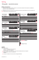
1H/1C System
(1 transformer)
Rc Power [1]
R [R+Rc joined by jumper loop]
Y Compressor contactor
C 24VAC common
W Heat relay
G Fan relay
Heat-only System
Rc Power [1]
R [R+Rc joined by jumper loop]
C 24VAC common
W Heat relay
1H/1C System
(2 transformers)
Rc Power (cooling transformer) [1, 2]
R Power (heating transformer) [1, 2]
Y Compressor contactor
C 24VAC common [3]
W Heat relay
G Fan relay
Heat-only System
with Fan
Rc Power [1]
R [R+Rc joined by jumper loop]
C 24VAC common
W Heat relay
G Fan relay
Cool-only System
Rc Power [1]
R [R+Rc joined by jumper loop]
Y Compressor contactor
C 24VAC common
G Fan relay
2H/2C System
(1 transformer)
Rc Power [1]
R [R+Rc joined by jumper loop]
Y Compressor contactor (stage 1)
C 24VAC common
W Heat relay (stage 1)
G Fan relay
W2 Heat relay (stage 2)
Y2 Compressor contactor (stage 2)
2H/2C System
(2 transformers)
Rc Power (cooling transformer) [1, 2]
R Power (heating transformer) [1, 2]
Y Compressor contactor (stage 1)
C 24VAC common [3]
W Heat relay (stage 1)
G Fan relay
W2 Heat relay (stage 2)
Y2 Compressor contactor (stage 2)
See [notes] below
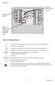
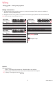
Wiring
Wiring guide — conventional systems
NOTES
Wire specifications:
Use 18- to 22-gauge thermostat wire.
Shielded cable is not required.
[1] Power supply. Provide disconnect means and overload protection as required.
[2] Remove jumper loop for 2-transformer
systems.
[3] Common connection must come from cooling transformer.
Y2GY LW2
MCR34821
RKC WRc
Y2GY LW2
MCR34822
RKC WRc
Y2GY LW2
MCR34824
RKC WRc
Y2GY LW2
MCR34825
RKC WRc
Y2GY LW2
MCR34826
RKC WRc
Y2GY LW2
M34823
RKC WRc
Y2GY LW2
M34827
RKC WRc
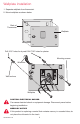
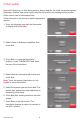
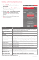
Wiring Instructions
1. This thermostat requires a 24Vac common to power the thermostat. The K terminal is available for
Wiresaver module (THP9045A1023).
2. Straighten the wire. Using a pen tip to hold down the terminal, gently slide the wire into terminal hole.
Note: Terminal hole will only accept one wire.
Y2GY LW2
MCR34821
RKC WRc
Jumper Loop