4500 THERMOSTAT INSTALLATION INSTRUCTIONS N7970 7/97
Table of Contents Section 1. GENERAL DESCRIPTION ................................................................................1-1 Application and Description..............................................................................1-1 4500 Specifications ............................................................................................1-2 Section 2. Front Panel Controls ........................................................................................2-1 Description ..................
S E C T I O N 1 General Description • • • • • • • • • • • • • • • • • • • • • • • • • • • • • • • • • • • • • • • • • • In This Section ♦ Application and Description ♦ 4500 Specifications • • • • • • • • • • • • • • • • • • • • • • • • • • • • • • • • • • • • • • • • • • Application and Description The Ademco 4500 thermostat provides control for both heat and air conditioning. The Ademco 4286 Phone Module is required in the installation for use with the 4500 thermostat.
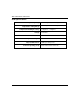
500 Installation Instructions 4500 Specifications Operating Range Temperature Setting Range Temperature Reading Accuracy Voltage Current Draw Air Conditioner Compressor Off Cycle Physical Dimensions Control loop rating (each) 1-2 32 to 122 degrees F., 0 to 50 degrees C. 45 to 99 degrees F., 7 to 37 degrees C. ± 2 degrees F., ± 1 degree C. 11 to 14VDC 50 mA 5 minutes minimum 6-3/16” by 2-7/8” by 1-1/4” 24VAC RMS nominal at 500 mA.
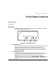
S E C T I O N 2 Front Panel Controls • • • • • • • • • • • • • • • • • • • • • • • • • • • • • • • • • • • • • • • • • • In This Section ♦ Description • • • • • • • • • • • • • • • • • • • • • • • • • • • • • • • • • • • • • • • • • • Description Referring to Figure 1 below, there are two controls and one status indicator on the front panel of the thermostat. HEAT <> COOL BYPASS <> ACTIVE 1 2 3 Figure 1.
4500 Thermostat Installation Instructions You will not be able to adjust room temperature by phone when the 4500 is bypassed. There are several uses for the BYPASS switch function: • Allows the user to go back to their pre-existing thermostat at any time. • Allows heating/air conditioning service people to bypass the 4500 during HVAC servicing and maintenance. The 4500 is out of the HVAC control circuit when bypassed.
S E C T I O N 3 Installing the 4500 Thermostat • • • • • • • • • • • • • • • • • • • • • • • • • • • • • • • • • • • • • • • • • • In This Section ♦ General ♦ Mounting and Installation ♦ Wiring Connections ♦ Step-by-Step Installation Instructions ♦ Setting the DIP Switch ♦ Setting the Fan Control Pins • • • • • • • • • • • • • • • • • • • • • • • • • • • • • • • • • • • • • • • • • • General Information The 4500 is controlled by a four-wire interface from the 4286 VIP Module and is powered by 12VDC auxi
4500 Thermostat Installation Instructions While installation of the 4500 is possible without the services of a HVAC contractor, some installers will prefer to have an HVAC contractor connect the 4500 to the HVAC system and test its operation. This is recommended if you do not have HVAC experience. In cases where you prefer to do the entire installation, it is suggested that the HVAC contractor be contacted for information on the type of heating system and the amount of “span” (i.e.
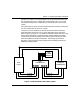
Section 3. Installing the 4500 Thermostat Sometimes, R and Rc are jumpered together at the premises thermostat and are connected to the HVAC system with a single common wire. This is the case if both heating and air conditioning are controlled by the same control system. The remaining three wires connect the thermostat to the heating, cooling and fan control loop inputs of the HVAC system.
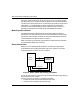
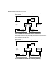
4500 Thermostat Installation Instructions If you are installing the 4500 in a heat only system, the setup will look like Figure 4 below. 4286 PHONE MODULE R R 4500 THERMOSTAT HVAC System 6 8 5 PREMISES THERMOSTAT 3 IN OUT G W Heat (W) Heat (W) Fan (G) Fan (G) Figure 4. 4500 Thermostat with Heating System Only Some heating systems, such as the forced-air type, have a fan (connections are shown). Other heat-only systems may not include a fan, in which case the fan connections are not used.
Section 3. Installing the 4500 Thermostat When installing the 4500 thermostat, refer to the Summary of Connections at the back of this manual. This diagram depicts the 4500's terminal strip and shows exactly how the thermostat must be wired. The heating/cooling system and thermostat you are working on may not have all the connections shown. All heating systems have R and W connections. Heating systems with a fan control have the G connection.
4500 Thermostat Installation Instructions 5. Connect the tagged wires removed in step 4 from the HVAC system to the applicable terminals of the 4500. Refer to the following table for proper connection information. Table 1 Lead from HVAC system Terminal on 4500 Fan (green) (G) 8 Cool (yellow) (Y) 7 Heat (white) (W) 6 6. Connect a wire to each of the vacant terminals on the premises thermostat that you noted in step 4 above, and make a run from those terminals to the 4500.
Section 3. Installing the 4500 Thermostat 9. Connect the 4500 to the 4286 phone module using the supplied keypad type cable.
4500 Thermostat Installation Instructions 10. Once the 4500 is mounted, you need to set its DIP switch and 3-pin fan control jumper. These procedures are described below. Setting the DIP Switch The 4500 includes a DIP switch for setting the address of the thermostat. The 4286 phone access module can include up to 2 thermostats per system. These are referred to as thermostats 1 and 2. Set thermostat #1 DIP switch to address 01.
Section 3. Installing the 4500 Thermostat Setting the Fan Control Pins The three fan control pins in the center of the 4500 are used to control the operation of the HVAC system’s fan. Using the jumper provided, you can select whether or not the system’s fan should turn on with cooling and heating, or turn on only with cooling. The operation of the fan depends upon which two pins the jumper is installed on. If you want the fan to turn on with cooling only, place the jumper provided between pins 2 and 3.
4500 Thermostat Installation Instructions 3-10
S E C T I O N 4 Programming the 4286 to Add 4500 Thermostat(s) • • • • • • • • • • • • • • • • • • • • • • • • • • • • • • • • • • • • • • • • • • In This Section ♦ General ♦ To Enter and Use the 4286 Programming Mode ♦ Programming Fields ♦ Step-by-Step Programming Instructions ♦ Thermostat Voice Descriptor Vocabulary • • • • • • • • • • • • • • • • • • • • • • • • • • • • • • • • • • • • • • • • • • General To install the 4286 with 4500 thermostats, you must program the 4286 using its installer program
4500 Thermostat Installation Instructions To Enter and Use the 4286 Programming Mode: 1. Pick up a premises touch tone phone connected to the 4286 handset output. 2. Enter the 2 digit phone code on the phone keypad. If the 4286 is announcing, wait until system status announcements have been completed, then press # 98. The 4286 will announce the contents of programming field 00. New data may be entered into each field once the field contents are announced.
Section 4. Programming the 4286 to Add Thermostat(s) If The System Contains Thermostat Speaker Addressable Keypad NonAddressable Keypad Select “MUTE” (4286 #97 Mode) 01 - 30 31 No Assign 4500 to same partition as keypad 31 Yes Assign 4500 to same partition as keypad 00 00 No [default] [default] (exclude 04)* Thermostat 01 - 30 No Speaker (exclude 04)* No Thermostat No Speaker Comments *Do NOT select 04, which is the address of the 4286 Phone Module.
4500 Thermostat Installation Instructions Field 02: Control Panel Type 1 = Vista-10 and Vista-10SE, Via-30P and Via-30PSE, 4140XMP (with voice upgrade EPROM) 2 = Vista-20, Vista-20HW and Vista-20SE [default] 4 = Vista-40, Vista-50P, Vista-100, and Vista-120. Field 03: Units of Temperature 0 = temperatures in degrees F. [default] 1 = temperatures in degrees C. If an existing system has its temperature units changed, temperature(s) must be reprogrammed to reflect the new values.
Section 4. Programming the 4286 to Add Thermostat(s) The first digit indicates the swing above the set point; the second digit indicates the swing below the set point, as indicated below: Temperature Span (Swing) “ABOVE Digit #1 1= 2= 3= 4= 5= 6= 7= 0.0 deg. F. (0.0 deg. C.) +0.5 deg. F. (0.3 deg. C.) +0.75 deg. F. (0.4 deg. C.) +1.0 deg. F. (0.6 deg. C.) +1.5 deg. F. (0.8 deg. C.) +2.0 deg. F. (1.1 deg. C.) +2.5 deg. F. (1.4 deg. C.) “BELOW” Digit #2 1= 2= 3= 4= 5= 6= 7= 0.0 deg. F. ( 0.0 deg. C.
4500 Thermostat Installation Instructions For Fields 07-09, select the 3-digit word codes from Table 5 for each descriptor. If you want less than a 3-word description for the thermostat, set unused descriptors to 0 0 0. Note: Fields 07 through 09 select a voice announcement to be associated with thermostat #1. For example, if you wanted a voice announcement for “south bedroom temperature,” you would program Field 07 as 155; Field 08 as 015; and Field 09 as 158.
Section 4. Programming the 4286 to Add Thermostat(s) The first digit indicates the swing above the set point; the second digit indicates the swing below the set point, as indicated below: Temperature Span (Swing) “ABOVE Digit #1 1= 2= 3= 4= 5= 6= 7= 0.0 deg. F. (0.0 deg. C.) +0.5 deg. F. (0.3 deg. C.) +0.75 deg. F. (0.4 deg. C.) +1.0 deg. F. (0.6 deg. C.) +1.5 deg. F. (0.8 deg. C.) +2.0 deg. F. (1.1 deg. C.) +2.5 deg. F. (1.4 deg. C.) “BELOW” Digit #2 1= 2= 3= 4= 5= 6= 7= 0.0 deg. F. ( 0.0 deg. C.
4500 Thermostat Installation Instructions For Fields 13-15, select the 3-digit word codes from Table 5 for each descriptor. If you want less than a 3-word description for the thermostat, set unused descriptors to 0 0 0. Note: Fields 13 thru 15 select a voice announcement to be associated with thermostat #2. For example, if you wanted a voice announcement for “central hall temperature,” you would program Field 13 as 089; Field 14 as 050; and Field 15 as 158.
Section 4. Programming the 4286 to Add Thermostat(s) THERMOSTAT VOICE DESCRIPTORS VOCABULARY (4286 Phone Access Module Only) The following three digit codes are used to program thermostat descriptors into the 4286 programming fields 07 thru 09 and fields 13 thru 15.
4500 Thermostat Installation Instructions 4-10
S E C T I O N 5 Testing the 4500 With the 4286 • • • • • • • • • • • • • • • • • • • • • • • • • • • • • • • • • • • • • • • • • • In This Section ♦ General ♦ Step-by-Step Testing Procedure ♦ Setting the Premises thermostat ♦ Setting the 4500 Thermostat ♦ Menu Selections • • • • • • • • • • • • • • • • • • • • • • • • • • • • • • • • • • • • • • • • • • General Once the 4500 has been installed, and the 4286 programmed, the system may be tested with the following procedure.
4500 Thermostat Installation Instructions 5. Check the heat mode operation of the premises thermostat by varying its set point and verifying that the heating system turns on and off. 6. If the 4500 thermostat will control an air conditioning system, set the 4500 front panel slide switches to ACTIVE and COOL. Set the premises thermostat into its cool mode as well. If only heating will be controlled, skip to step 9. 7. Set the premises thermostat 10 degrees below the present room temperature.
Section 5. Testing the 4500 With the 4286 Phone Module 2. Obtain phone access from the phone module. Enter the 2-digit phone code. Enter the 4-digit system code if prompted. 3. Press # 99 on the phone keypad after the complete status announcement. 4. The 4286 will announce: “Thermostat Mode.” The temperature setting for thermostat #1 will follow. You can change its set point using menu selection 1 below. If thermostat #1 is in BYPASS or CHECK, that status will be announced instead of the set point.
4500 Thermostat Installation Instructions “For set-back on/off, enter 3.” Turning off set-back will result in it remaining disabled while armed away, until the next time the system is disarmed. This feature allows the user to turn off the set-back before returning home, so that the premises will have time to return to a comfortable at-home temperature. It also allows the user to turn off set-back before leaving home, when they plan to be away only a short time.
S E C T I O N 6 Troubleshooting • • • • • • • • • • • • • • • • • • • • • • • • • • • • • • • • • • • • • • • • • • In This Section ♦ General ♦ Troubleshooting Typical Thermostat Set-Up Problems • • • • • • • • • • • • • • • • • • • • • • • • • • • • • • • • • • • • • • • • • • General Following the procedures in the 4286 Installation Instructions manual should result in a minimum number of system problems.
4500 Thermostat Installation Instructions 4500 or premises thermostat fails to control the HVAC system. 1. Check set points in 4500 and premises thermostat to ensure they are set properly. 2. If BYPASS of 4500 via its front panel switch causes existing thermostat to work properly, then problem is in the 4500 wiring or within the 4500 itself. If the existing thermostat does not work, check its wiring and battery, if any. 3. Check wiring connections. Refer to Summary of Connections diagram.
S E C T I O N 7 Appendices • • • • • • • • • • • • • • • • • • • • • • • • • • • • • • • • • • • • • • • • • • In This Section ♦ Federal Communications Commission (FCC) Part 15 Statement ♦ Ademco Limited Warranty ♦ Summary of Connections • • • • • • • • • • • • • • • • • • • • • • • • • • • • • • • • • • • • • • • • • • FEDERAL COMMUNICATIONS COMMISSION (FCC) PART 15 STATEMENT This equipment has been tested to FCC requirements and has been found acceptable for use.
4500 Thermostat Installation Instructions ADEMCO Limited Warranty Alarm Device Manufacturing Company, a Division of Pittway Corporation, and its divisions, subsidiaries and affiliates (“Seller”), 165 Eileen Way, Syosset, New York 11791, warrants its products to be in conformance with its own plans and specifications and to be free from defects in materials and workmanship under normal use and service for 24 months from the date stamp control on the product or, for products not having an Ademco date stamp,
Appendices Heat Fan } TO PREMISES THERMOSTAT Cool Fan Cool Red Black Yellow } TO 4286 VOICE MODULE 54321 1 2 3 4 5 6 7 8 9 10 1 1 1 2 } DOWN UP TO HVAC SYSTEM Green Heat Two jumper wires are factory installed between screw terminals 1-3 and 2-4. Replace if missing. DIP SWITCH } SHOWN SET TO 01 1 2 3 FAN CONTROL PINS TEMPERATURE JUMPER PLACED ON 1 and 2 = FAN ON WITH HEAT AND COOL SENSOR JUMPER PLACED ON 2 and 3 = FAN ON WITH COOL ONLY 4500 Thermostat Summary of Connections .
165 Eileen Way, Syosset, New York, 11791 Copyright © 1997 PITTWAY CORPORATION N7970 7/97