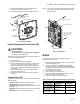
VisionPRO® IAQ Total Home Comfort System PRODUCT DATA FEATURES • Large, clear display with backlight shows the current and set temperature and time—even in the dark. • Touchscreen interaction • Real-time clock keeps time during power failures and automatically updates to daylight savings. • Change/check reminders let you know when to service or replace filters. • Various Hold options allow you to override the program schedule, as desired.
VISIONPRO® IAQ TOTAL HOME COMFORT SYSTEM SPECIFICATIONS Finish: VisionPRO® IAQ Thermostats: Premier White® color. THM5421C1008: Premier White® color. C7189U1005 Wall Mount Remote Indoor Sensor: Premier White® color.
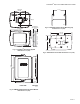
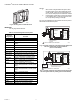
VISIONPRO® IAQ TOTAL HOME COMFORT SYSTEM WALLPLATE 3-3/8 (86) 1-1/2 (38) 3-3/8 (86) M4488 THERMOSTAT 6 (152) Fig. 3. C7089U1006 Outdoor Sensor Mounting Clip dimensions in in. (mm). THERMOSTAT AND WALLPLATE 1-3/8 (35) 7-7/8 (200) 3-5/16 (84) 4-9/16 (116) 5-1/2 (140) 3-5/16 (84) M23539 Fig. 1. VisionPRO® IAQ Comfort System dimensions in in. (mm). M22139 Fig. 4. 32003796-001 Cover Plate dimensions in in. (mm).
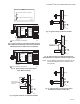
VISIONPRO® IAQ TOTAL HOME COMFORT SYSTEM 2-9/32 (58) 2-9/32 (58) M23522 1-1/2 (38) 45/64 (18) FRONT VIEW SIDE VIEW 1-1/2 (38) FRONT VIEW (COVER OFF) Fig. 5. C7189U1005 Remote Indoor Sensor dimensions in in. (mm). INSTALLATION When Installing this Product... 1. 2. 3. 4. Read these instructions carefully. Failure to follow the instructions can damage the product or cause a hazardous condition. Check the ratings given in the instructions to make sure the product is suitable for your application.
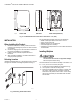
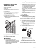
VISIONPRO® IAQ TOTAL HOME COMFORT SYSTEM 4. 5. NOTE: It is normal for the LED to blink continuously during startup, and while checking equipment status (Auto Discover mode). Position the wallplate over the holes, pulling wires through the wiring opening. See Fig. 7. Insert the mounting screws into the holes and tighten. WALL WIRES THROUGH WALL AND WIRE SLOT WALL ANCHORS (2) WALL ANCHOR COMMUNICATION LED MOUNTING HOLES DRILL 3/16 IN. HOLES FOR DRYWALL. DRILL 7/32 IN.
VISIONPRO® IAQ TOTAL HOME COMFORT SYSTEM NOTES: 1. 2. When used in a single-transformer system, leave the metal jumper wires in place between R and Rc, and Rc and Rh. If used on a two-transformer system, remove metal jumper wire between Rc and Rh. If thermostat is configured for a heat pump system in the Installer Setup, configure changeover valve for cool (O-factory setting) or heat (B). For wiring to a W8835 Zone panel please refer to the product data sheet included with the panel. M23541 Fig. 9.
VISIONPRO® IAQ TOTAL HOME COMFORT SYSTEM KEY 1 2 = NORMALLY OPEN, DRY CONTACTS 3 C R 24 VAC RC = NORMALLY CLOSED, DRY CONTACTS RH M23685 POWERED HUMIDIFIER 1 1 1 2 2 3 3 C R COMMUNICATION LED COMMUNICATION CONV. HP TERMINALS W1 O/B W2 AUX 24 VAC W3 AUX2 Y Y RC Y2 Y2 RH G G HEAT 2 RELAY M23490 HEAT 3 RELAY Fig. 15. Typical hookup of powered humidifier. COOL 1 RELAY COOL 2 RELAY 1 2 3 C WIRE TO TERMINALS ON THERMOSTAT. M23487 R Fig. 12.
VISIONPRO® IAQ TOTAL HOME COMFORT SYSTEM POWER THE THERMOSTAT 1 2 • 24 Vac common wire only to EIM or zone panel. 3 Wiring 24 Vac Common 24 VAC R RC FIELD INSTALLED JUMPER BETWEEN R AND VNT 1 • Single-Transformer System—Connect the common side of the transformer to the C screw terminal of the EIM. Leave the metal jumper wires in place between R, Rc, and RH. • Two-Transformer System—Connect the common side of the cooling transformer to the C screw terminal of the EIM.
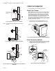
VISIONPRO® IAQ TOTAL HOME COMFORT SYSTEM Locate and Mount C7089U1006 Outdoor Temperature Sensor (Optional) Mount the sensor where (see Fig. 23): • cannot tamper with settings. • there is good air circulation. • it can measure true outdoor ambient temperature. • surface is flat. • wire distance between C7089U1006 and EIM is less than 200 feet. IMPORTANT Erratic temperature readings from a sensor can occur as a result of any of the wiring practices described below.
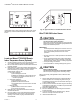
VISIONPRO® IAQ TOTAL HOME COMFORT SYSTEM MON FAN TUE WED THU FRI SAT AT SUN YES Inside NO Set To AUTO NO Following Schedule SYSTEM 5 FEET (1.5 METERS) Outside HEAT NO AM SCHED HOLD CLOCK SCREEN MORE M4476 M22453 If thermostat is set to Auto Changeover System mode, press the More key until the outside temperature is shown on the screen. MON TUE WED THU FRI SAT Fig. 25. Typical location for C7189U1005 Indoor Sensor.
VISIONPRO® IAQ TOTAL HOME COMFORT SYSTEM • The thermostat will display the temperature measured at the sensor locations (internal thermostat sensor is disabled). Sensors must be in square numbers (e.g., 4, 9, 16, and so on) and the displayed temperature will be an average of the temperatures measured at each location. • The thermostat will display a 50-50 average of the temperature measured at the thermostat location and the average of the temperatures measured at the remote indoor sensor locations.
VISIONPRO® IAQ TOTAL HOME COMFORT SYSTEM 1. Press and release the System Key. USE ARROWS TO SET YEAR AND TIME MO WE W TH FR SA THU SU FAN ON Inside AUTO Following Schedule SYSTEM EM HEAT OFF A M COOL SCHED HOLD Humidity CLOCK SCREEN DONE M22425 M23498 2. INSTALLER SETUP Auto Discover is available when the TH9421C thermostat is connected to an EIM. The EIM communicates information to the thermostat.
VISIONPRO® IAQ TOTAL HOME COMFORT SYSTEM 4. See screen below to review how the thermostat keys are used during Installer Setup. See Table 3–4 for the Installer Setup Numbers and Settings. ADVANCE TO NEXT INSTALLER SETUP INSTALLER SETUP NUMBER MON CURRENT SETTING WED THU U FRI SAT AT SUN DONE O PRESS TO EXIT INSTALLER SETUP 5. CHANGE THE CURRENT SETTING M22443 Press the Done key to exit the Installer Setup screen. Table 3. Installer Setup Menu.
VISIONPRO® IAQ TOTAL HOME COMFORT SYSTEM Table 3. Installer Setup Menu. (Continued) ISU Parameter Number Installer Setup Name Settings (Factory Defaults Shown in Bold) Notes 200 Back-up Heat 0 Source Applies to 1 both Aux and E EmHeat Electric backup heat Fossil fuel backup heat Auto Discover Only shown if ISU172 = 2 and ISU176 = 1 or greater. 210 External Fossil Fuel Kit 0 1 Thermostat controls backup heat External Fossil Fuel kit controls backup heat Only shown if ISU172 = 2 and ISU200 = 1.
VISIONPRO® IAQ TOTAL HOME COMFORT SYSTEM Table 3. Installer Setup Menu. (Continued) ISU Parameter Number Installer Setup Name Settings (Factory Defaults Shown in Bold) 0 1 2 Notes 345 Dual Fuel Heat Pump Control Balance point only See Dual Fuel Heat Pump control on page 22. Balance point plus 2° droop Balance point/auxiliary heat lockout plus 2° droop.
VISIONPRO® IAQ TOTAL HOME COMFORT SYSTEM Table 3. Installer Setup Menu. (Continued) ISU Parameter Number Installer Setup Name Settings (Factory Defaults Shown in Bold) Hum Fan Action 379 Dehumidification 0 Control 1 3 383 Over-Cooling Limit 384 Dehumidification 0 Fan Action 1 System fan turns on with dehumidifier Only shown if ISU379 = 3. Dehumidifier operates independent of system fan 390 Southern 0 Dehumidification 1 Away Mode No Yes Not shown if ISU379 = 0.
VISIONPRO® IAQ TOTAL HOME COMFORT SYSTEM Table 3. Installer Setup Menu. (Continued) ISU Parameter Number Installer Setup Name Settings (Factory Defaults Shown in Bold) Notes Furnace Filter Change Reminder 502 Furnace filter 0 reminder run time 1 equipment counts Counts runtime Heat and Cool Counts runtime Cool only 510 USU Humidifier Pad Replacement Reminder 0 1 2 3 E Disabled 90 C Days or 30 R.T. Days 180 C Days or 60 R.T. Days 365 C Days or 90 R.T.
VISIONPRO® IAQ TOTAL HOME COMFORT SYSTEM Table 3. Installer Setup Menu. (Continued) ISU Parameter Number 700 Installer Setup Name Temperature Display Offset Settings (Factory Defaults Shown in Bold) -3 -2 -1 0 1 2 3 701 Humidity Display -5 Offset -4 -3 -2 -1 0 1 2 3 4 5 -5% -4% -3% -2% -1% 0% 1% 2% 3% 4% 5% 710 Restore Factory Defaults No Yes 0 1 Notes -3°F -1.5°C -2°F -1°C -1°F -.5°C 0°F 0. °C — (no difference in displayed temperature and actual room temperature) 1°F .5°C 2°F 1°C 3°F 1.
VISIONPRO® IAQ TOTAL HOME COMFORT SYSTEM Installer System Tests Table 4. Installer System Test.
VISIONPRO® IAQ TOTAL HOME COMFORT SYSTEM System and Fan Settings 1. 2. System The System key selections vary based on your heating and/or cooling system type. 3. Press the More key until the inside humidity level setpoint is shown. Use Up and Down arrow keys, located to the right of the humidity setpoint, to set desired humidity level. Press Done key. Control Dehumidification Level Heat — Thermostat controls the heating system.
VISIONPRO® IAQ TOTAL HOME COMFORT SYSTEM DEHUMIDIFICATION DROOP CONTROL In extremely high humidity conditions, the thermostat keeps the air conditioner running (energizing Y/Y2 and G) for up to 3°F below the temperature setpoint. It does this while trying to achieve the desired humidity setpoint and balancing that with the temperature setpoint. The thermostat controls up to 3° F below the temperature setting until either the humidity setpoint is satisfied or conditions change.
VISIONPRO® IAQ TOTAL HOME COMFORT SYSTEM Heat Pump Emergency Heat LED Indication The thermostat uses a red LED indicator that lights when the thermostat is in the Emergency Heat mode. The LED is located in the upper right corner of the thermostat. It is visible only when on.
OUTDOOR TEMPERATURE VISIONPRO® IAQ TOTAL HOME COMFORT SYSTEM Operation in Emergency Heat Mode COMPRESSOR ONLY 50 BOTH COMPRESSOR AND AUXILIARY HEAT 35 AUXILIARY ONLY Once the thermostat is placed into the Emergency Heat mode, the compressor and auxiliary lockout features are turned off. In the Emergency heat mode, the compressor is locked out. The first stage of heat is whatever is connected to the AUX terminal. The second stage of heat is connected to the AUX2. terminal.
VISIONPRO® IAQ TOTAL HOME COMFORT SYSTEM Table 7. Indoor Air Quality Operation. Last call System Setting Auto Call For Action Humidification HUM1 and HUM2 Closea Nothinga Energize terminals None Auto Dehumidification Nothingb DHM1 and DHM2 closee None Auto Dehumidification Auto Heat or Em.Heat Heat or Em.Heat Ventilation Humidification Dehumidification Nothingb VNT1 and VNT2 Close HUM1 and HUM2 Close Yc and Gc None None None Heat or Em.
VISIONPRO® IAQ TOTAL HOME COMFORT SYSTEM 4. See the screen below to review how the thermostat keys are used during the User Setup. See Table 8 for the User Setup numbers and settings. ADVANCE TO NEXT USER SETUP USER SETUP NUMBER MON CURRENT SETTING WED THU U FRI SAT AT 5. CHANGE THE CURRENT SETTING 520 M19922 Press the Done key to exit the User Setup screen. User Setup User Setup No.
VISIONPRO® IAQ TOTAL HOME COMFORT SYSTEM back to a comfortable temperature. Sleep—Period when you are asleep and want an energysaving temperature. MON FAN ON AUTO CIRC NOTE: Schedule times are in 15-minute intervals. Edit Schedule 1. TUE WED THU FRI SAT HEAT CANCEL PERIOD Press Sched key. AM COOL FRI FAN Inside Set DONE AUTO Following Schedule 4. HEAT 5. AM PM Humidity SCHED HOLD CLOCK 6. 7. 8. 9. Press Edit key.
VISIONPRO® IAQ TOTAL HOME COMFORT SYSTEM TUE MON WED THU FRI SAT Fan Control SUN If the Fan program is scheduled, Auto is shown and any programmable mode that is set; for example, if during Wake period, Fan is set to Auto, only Auto is shown in the Fan area. However, if during the Wake period, fan is scheduled to On, both Auto and On are shown. Auto indicates fan is running its schedule; On indicates Fan schedule is set to On.
VISIONPRO® IAQ TOTAL HOME COMFORT SYSTEM OPERATE VISIONPRO® IAQ 3. NOTE: Once “Hold Temperature Until” time is reached, the thermostat shows “Following Schedule” on the screen to indicate that “Temporary Hold” has ended. Set Time 1. 2. Press the Cancel or Sched key to cancel “Hold Temperature Until” and resume schedule. Press Clock. Use arrows to set current time. PERMANENT HOLD Permanent Hold changes the temperature setting until Permanent Hold is cancelled. TUE 1. 2. Press Hold key.
VISIONPRO® IAQ TOTAL HOME COMFORT SYSTEM 4. 4. To cancel the Vacation Hold override early, press the Cancel key. NOTE: When the number of days of Vacation Hold expires, the screen shows “Following Schedule” to indicate that Vacation Hold has ended. Screen Locks TUE SOUTHERN DEHUMIDIFICATION AWAY SETTING Southern Dehumidification Away Setting is an option that only appears if ISU number 390 is set to yes.
VISIONPRO® IAQ TOTAL HOME COMFORT SYSTEM If you don’t have a dehumidifier, the thermostat activates the air conditioner to reduce humidity (may cool as much as 3°F lower than your temperature setting). 1. 2. 3. 1. Press MORE until the dehumidifier screen is displayed. Press the Up or Down arrow to set the desired humidity level and operation (Auto or Off). Press DONE to save and exit, or press CANCEL to exit without saving changes. Press the More key until the filter reminder appears on the screen.
VISIONPRO® IAQ TOTAL HOME COMFORT SYSTEM 5. Press the Reset key to activate the new number of days selected in the previous screen. MON TUE WED THU FRI SAT NOTE: While the reminder is set according to calendar days, the display shows the equivalent run time days. SUN MON CHANGE FILTER UV LAMP HUMIDIFIER PAD TUE WED SA HOLD WAKE CLOCK LEAVE DAYS SCREEN RETURN MORE SLEEP CANCEL DONE SCHED EDIT HOLD WAKE CLOCK LEAVE SCREEN RETURN MORE SLEEP M22451 6.
VISIONPRO® IAQ TOTAL HOME COMFORT SYSTEM NOTE: It takes about a week for the thermostat to adjust to local weather, the schedule, the construction of the home and the heating and/or cooling system. Each day it adjusts the next day’s recovery start time accordingly. Minimum Off-Timer P+I Control If there is a call during the minimum-off timer, the thermostat shows “Wait” in the display.
VISIONPRO® IAQ TOTAL HOME COMFORT SYSTEM TUE MON WED THU FRI SA Table 12. Sensor Resistance at Outdoor Temperature. SUN Outdoor Temperature Inside SCHED DONE HOLD WAKE CLOCK LEAVE SCREEN RETURN SLEEP CANCEL M23679 C7089U1006 Outdoor Temperature Sensor Operation When installed with Thermostat Installer Setup Number 0342 set to 1, the outside temperature can be displayed on the thermostat. See Fig. 34.
VISIONPRO® IAQ TOTAL HOME COMFORT SYSTEM installed with Thermostat Installer Setup Number 340 set to 2, the temperature displayed on the thermostat home screen as Inside Temperature will be a 50/50 average between the temperature sensed at the remote sensor location and the temperature sensed at the thermostat location. The C7189U1005 Wall Mount Temperature Sensor converts room temperature to a resistance that the thermostat can interpret.
VISIONPRO® IAQ TOTAL HOME COMFORT SYSTEM TROUBLESHOOTING Table 15. Troubleshooting. Symptom Possible Cause Action Display does not come on Thermostat is not being powered Check if the thermostat is mounted and latched on the wall plate. If not: — Mount and latch the thermostat on the wallplate. Check if the circuit breaker is tripped or the fuse is blown; if it is: — Reset the circuit Breaker or replace the fuse.
VISIONPRO® IAQ TOTAL HOME COMFORT SYSTEM Table 15. Troubleshooting. (Continued) Symptom Cooling does not turn on (“Cool On” is solid in the display) Possible Cause Action Cooling Equipment failure Check for 24 Vac at the equipment on the secondary side of the transformer between power and common. If voltage is not present check the cooling equipment to find the cause of the problem. Check for 24 Vac between the cool terminal(s) on the equipment interface Module and transformer common.
VISIONPRO® IAQ TOTAL HOME COMFORT SYSTEM Table 15. Troubleshooting. (Continued) Symptom Possible Cause Action Heat On is not in the display. System setting is not set to Heat Set the system setting to Heat and set the temperature and/or temperature setting is not set setting above the room temperature. above room temperature. Cool On is not in the display. System setting is not set to Cool and/or the temperature setting is not set below room temperature.
VISIONPRO® IAQ TOTAL HOME COMFORT SYSTEM COMPATIBILITY Recommend the following products for use with the VisionPRO® IAQ. Table 16. Humidifiers HE440A1005—Powered Steam Humidifier with 13 gpd capacity HE365A1006—Powered Bypass Flow-through humidifier with 18 gpd capacity HE265A1007—Bypass Flow-through humidifier with 17 gpd capacity HE225A1006—Bypass Flow-through humidifier with 12 gpd capacity Table 17. Dehumidifier DH90A1007—90 Pint Whole House Dehumidifier Table 18.
VISIONPRO® IAQ TOTAL HOME COMFORT SYSTEM 39 68-0287—1
VISIONPRO® IAQ TOTAL HOME COMFORT SYSTEM Automation and Control Solutions Honeywell International Inc. Honeywell Limited-Honeywell Limitée 1985 Douglas Drive North 35 Dynamic Drive Golden Valley, MN 55422 Toronto, Ontario M1V 4Z9 customer.honeywell.com ® U.S. Registered Trademark © 2006 Honeywell International Inc. US Patent No. 6,208,263; 6,373,376; 6,448,901; 6,926,076; 7,044,397; D509151; H25192; H25193 and other patents pending 68-0287—1 M.S. Rev.