evohome Installation Guide
Icon key evohome Central Controller Wireless OpenTherm Bridge (R8810) Central Controller Wall Bracket (ATF300) Mixing Valve Controller (HM80) Central Controller Table Stand (ATF100 or ATF200) Room Temperature Sensor (HCW82) Radiator Controller (HR92) Room Temperature Sensor (HCF82) Radiator Controller (HR80) Digital Room Thermostat (DTS92) Wireless Relay Box (BDR91) Wireless Cylinder Thermostat Transceiver (CS92) Remote Access Gateway (RFG100) Wireless Cylinder Thermostat Strap-on Sensor (CS92
P1 Thanks for choosing evohome evohome means more comfort, and more control of the heating system. It’s simple to install and easy to use. Follow these instructions to set up the evohome system. Devices that need to be connected to the mains electricity supply should be installed by a competent person. Before you start Make sure you have all the devices you need for your system. If you used our ‘Design your evohome system’ guide, match each device to the room or zones in your plan.
P2 You have… a Base Pack or a Connected Pack + Un-bound devices Step 1: Wire up the heating system You have… an un-bound Central Controller + Un-bound devices You have… a Base Pack or a Connected Pack + No additional devices Step 1: Wire up your heating system Connect all mains powered devices to the heating system Step 2: Set up your Central Controller Power up the Central Controller and follow the on-screen instructions for your system Go to Installer Menu Go to Guided Configuration Step 3: Power
P3 evohome Installation Guide Step 1: Wire up the heating system evohome communicates using wireless on a robust 868Mhz signal that is unaffected by common remote controls or Wifi. Some devices need mains power or to be connected to external equipment and it's best to wire up these items first to simplify the binding process later in the setup. The evohome controller will give on screen instructions when these should be powered up.
Step 1: Wire up the heating system P4 Wireless Relay Box (BDR91) ! Turn off at mains and isolate the supply before starting If you’re fitting a Wireless Relay Box (BDR91) to your boiler, zone valve or Sundial valve 1 Mount the Wireless Relay Box on a non- metal surface at least 30cm from your boiler, other wireless device or metal objects 2 Release the clip on the bottom to open the front cover 3 Follow the wiring diagram (see Appendix: Figures 5-10) to connect the Wireless Relay Box to your boi
evohome Installation Guide P5 Wireless Cylinder Thermostat (CS92) If you’re fitting a Wireless Cylinder Thermostat (CS92) You will need to install the CS92 Transceiver and only one of the two sensors (CS92 Strapon Sensor or CS92 Insertion Sensor).
P6 Step 1: Wire up the heating system Wireless Cylinder Thermostat (CS92) continued To fit the CS92 Insertion Sensor 1 Fit in the cylinder immersion well with suitable fittings to provide strain relief and prevent accidental removal 2 If the sensor doesn’t fit tightly in the immersion well fill the space with heat-conductive compound to ensure maximum heat transfer 3 Install the CS92 Transceiver in a suitable location close enough for the cable from the sensor to reach 4 Connect the cable from
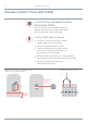
P7 evohome Installation Guide Remote Access Gateway (RFG100) If you’re fitting a Remote Access Gateway (RFG100) 1 Connect the Remote Access Gateway to the home’s internet router using the ethernet cable supplied
P8 Step 1: Wire up the heating system Mixing Valve Controller (HM80), Underfloor Heating Controller (HCE80/HCC80), Opentherm Bridge (R8810) If you’re fitting a Mixing Valve Controller (HM80), Underfloor Heating Controller (HCE80/HCC80), OpenTherm Bridge (R8810) Refer to the installation instructions supplied with each device
P9 evohome Installation Guide Step 2: Set up your Central Controller The Central Controller has a guided configuration process to help you set up the zones for a single type of system. For mixed systems (i.e. Under Floor Heating zones plus Radiator zones) use Guided Configuration for the larger system then “Add Zones” in the installer menu. To add a stored hot water system use the guided configuration Stored Hot Water option in the installer menu.
Step 2: Set up evotouch P10 Powering up your Central Controller ! Your Central Controller comes with *rechargeable batteries which are pre-charged allowing you to set-up the system while off the table stand or wall bracket. First, power up the Central Controller 1 Remove the cover, remove the battery tab and replace the cover 2 3 Once the batteries are fully charged, the Central Controller can be easily removed from the table stand or wall bracket for ease of programming.
P11 evohome Installation Guide Then to set up the Central Controller 1 Follow the on-screen instructions to set up the language, date and time 2 Now choose the correct option for the system you’re installing: For a Base Pack or a Connected Pack and NO additional devices we recommended pressing ‘Home’ – then go to "Step 4: System test" on page 29.
P12 Step 2: Set up evotouch
P13 evohome Installation Guide Step 3: Power up and bind devices If you bought a Base Pack or a Connected Pack only — your devices are already bound. Go to Step 4. If you bought an unbound Central Controller, plus other devices and are using ‘Guided Configuration’ follow the instructions on your Central Controller screen and use this section to put the devices into binding mode.
Step 3: Power up and bind devices P14 Radiator Controllers (HR92) Power up and bind Radiator Controllers (HR92) – Your evo Zone Kit Central Controller If you are NOT following GUIDED CONFIGURATION follow these steps on your Central Controller display first: Bind the Radiator Controllers (HR92) 1 Remove the circular top cover 2 Open the battery clip and insert the AA batteries supplied 3 Close the clip and replace the cover 3. Press ADD ZONE 4 Press the 4.
evohome Installation Guide P15 Install the Radiator Controllers (HR92) 1 Locate the room (zone) for the radiator controller 2 Slide the locking mechanism to the unlock position 3 Remove the adaptor from the bottom of the controller 4 Unscrew the black wheel fully anticlockwise 5 Remove any existing control on the radiator valve 6 Screw the white end of the adaptor on to the radiator valve 7 Push the controller fully on to the adaptor with the screen facing towards you 8 3 Slide the locki
Step 3: Power up and bind devices P16 Wireless Cylinder Thermostat (CS92) Central Controller If you are NOT following GUIDED CONFIGURATION follow these steps on your Central Controller display first: 1. Press and hold for 3 “Settings” seconds Power up and bind a Wireless Cylinder Thermostat Transceiver (CS92) On the CS92 Transceiver 1 Remove the CS92 Transceiver cover 2 Remove the battery tab and replace the cover 3 On the CS92 Transceiver press and hold the button for 5 seconds.
evohome Installation Guide P17 ! You may need to refer to the wiring diagrams in the Appendix To bind the Wireless Relay Box (BDR91) 1 On the Wireless Relay Box, press and hold the button for 15 seconds (until the red LED blinks rapidly) to clear any previous binding data 2 Press and hold the button again for 5 seconds (until the red LED blinks slowly) 3 On the Central Controller press the green bind button 4 You should receive a SUCCESS message on the Central Controller (if not go back and re
Step 3: Power up and bind devices P18 Remote Access Gateway (RFG100) Power up and bind a Remote Access Gateway (RFG100) ! If the Gateway was in the Connected Pack with evohome, it is already bound and there is no need follow these binding instructions. Connect the Gateway to the power supply and turn on the power.
evohome Installation Guide P19 Wireless Relay Box (BDR91) Central Controller If you are NOT following GUIDED CONFIGURATION follow these steps on your Central Controller display first: 1. Press and hold ‘Settings’ for 3 seconds 2. Press the green tick 3. Press SYSTEM DEVICES 4. Press the button next to ‘Boiler Demand’ 5.
Step 3: Power up and bind devices P20 Wireless Relay Box (BDR91) continued Central Controller If you are NOT following GUIDED CONFIGURATION follow these steps on your Central Controller display first: 1. Press and hold for 3 “Settings” seconds 2. Press the green tick 3. Press ADD ZONE 4. Press the zone you want to add the controller to 5. Rename the zone if required and/or press the green tick 6.
P21 evohome Installation Guide To bind a Room Temperature Sensor (HCW82 or HCF82) 1 Press the bind button on the bottom right hand corner of the unit once.
Step 3: Power up and bind devices P22 Radiator Controller (HR80) Central Controller If you are NOT following GUIDED CONFIGURATION follow these steps on your Central Controller display first: 1. On the Central Controller press and hold “Settings” for 3 seconds 2. Press the green tick 3. Press ADD ZONE 4. Press the zone you want to add the controller to 5.
P23 evohome Installation Guide To bind the actuator 6 Press the bind button on the Radiator Controller (if there are multiple HR80’s in the zone, do this to all of them). The screen should show a flashing RF icon 7 On the Central Controller press the green bind button 8 Check that (all) the Radiator Controllers display SYNC.
Step 3: Power up and bind devices P24 Underfloor Heating Controller (HCE80 or HCC80) Central Controller If you are NOT following GUIDED CONFIGURATION follow these steps on your Central Controller display once the underfloor heating controller and sensors have been fitted: 1. On the Central Controller press and for 3 hold “Settings” seconds 2. Press the green tick 3.
P25 evohome Installation Guide To bind a Room Temperature Sensor (HCW82 or HCF82) 1 Press the bind button on the bottom right hand corner of the unit once.
P26 Step 3: Power up and bind devices Underfloor Heating Controller (HCE80 or HCC80) continued Then on the underfloor controller 1 Press the bind button until the bind button light comes on and the zone number light flashes red 2 On the Central Controller, press the green bind button If the zone light turns solid green the binding is successful If the zone light turns solid red continue with these instructions 3 Press the back arrow on the Central Controller 4 Press the bind button on the Unde
evohome Installation Guide P27 Mixing Valve Controller (HM80) Central Controller Power up and bind a Mixing Valve Controller (HM80) If you are NOT following GUIDED CONFIGURATION follow these steps on your Central Controller display once the Mixing Valve Controller and sensor have been installed: A Mixing Valve Controller should only be fitted by a qualified fitter.
P28 Step 3: Power up and bind devices To bind a Room Temperature Sensor (HCW82 or HCF82) 1 Press the bind button on the bottom right hand corner of the unit once.
P29 evohome Installation Guide Step 4: System test Now that all the devices are bound to your Central Controller and installed in their final locations, check that the system works properly and that all the devices are responding to commands from the Central Controller. You can perform a simple functional check of the heating system by overriding the temperature of each zone to their minimum and maximum while listening for a response from the radiator (or zone) controllers and boiler.
Step 4: System test P30 Advanced RF communication check ! To save power the battery devices only communicate with the Central Controller every four minutes therefore the system may not respond immediately to a manual change. To check the RF signal strength between the wireless devices and the Central Controller go to RF COMMS CHECK in the Central Controller Installer Menu and test each wireless device.
P31 evohome Installation Guide Battery Powered Wireless Devices Battery powered devices need to be put into test mode to send and receive a test signal: Radiator Controller (HR92) 1 Press the button, the zone name is displayed 2 Press and hold the button again for 5 seconds 3 Turn the dial to display TEST 4 Press the button The Central Controller will display the signal strength (poor to excellent) and the Radiator Controller will display a signal strength bar and a rating from 1 (poor) to 5
P32 Step 4: System test Advanced RF communication checks continued Radiator Controller (HR80) 1 Separate the Radiator Controller from the adaptor on the radiator 2 Turn the adjustment dial clockwise (approx two full rotations) until TEST is displayed The Central Controller will display the signal strength (poor to excellent) – nothing on the Central Controller display means the Radiator Controller has not received a test signal from the Central Controller.
P33 evohome Installation Guide Digital Room Thermostat (DTS92) 1 Put Room Thermostat into standby mode (show icon) 2 Press up and down together for 3 seconds 3 Press down once, the display should say CONT 4 Press down for 3 seconds, the display should say TEST The Central Controller will display the signal strength (poor to excellent) and the Room Thermostat will display a signal strength rating from 1 (poor) to 5 (excellent) – 0 means the Room Thermostat has not received a test signal from the
P34 Step 4: System test Advanced RF communication check continued Room Temperature Sensor (HCF82 or HCW82) 1 Remove the cover from the sensor 2 Press and hold the bind button until the red LED goes off (approx 30 seconds) 3 The red LED will flash each time it sends a test message The Central Controller will display the signal strength (poor to excellent) – no flashing means the Temperature Sensor has not received a test signal from the Central Controller.
P35 evohome Installation Guide Wireless Cylinder Thermostat (CS92A) 1 Press the button on the Cylinder Thermostat transceiver 2 The green light should come on. If it doesn’t, reinsert the batteries and try again The Central Controller will display the signal strength (poor to excellent) and the transceiver should flash the red LED from 1 flash (poor) to 5 flashes (excellent) – no flashing means the transceiver has not received a test signal from the Central Controller.
P36 Step 4: System test
P37 evohome Installation Guide Configuration and modification Once you’ve completed these steps you’re ready to start using evo. You can also make parameter adjustments in the Central Controller to match the exact requirements of the heating system. The operation and functions of the each zone can also be adjusted. These can be found in the Installer Menu. Components can be added or replaced by editing the zones or system in the Installer menu.
P38 Configuration and modification Parameters and control features Once you’ve completed these steps you’re ready to start using evo. The user guide gives you instructions for personalising the settings on the Central Controller. You can also make parameter adjustments on your Central Controller to match the exact requirements of the heating system. These can be found in the Installer Menu.
P39 evohome Installation Guide Adding and replacing components in an existing system Adding and replacing components in an existing system 1 On the Central Controller press and hold “Settings” for 3 seconds 2 Press the green tick 3 To change a device in a zone press ZONE SETTINGS and select the zone name To add or change an actuator 4 Press the application button then next and follow the instructions to bind a new actuator 5 To change the sensor press the sensor button, select the type of se
P40 Configuration and modification
P41 evohome Installation Guide Appendix Wiring diagrams, heating system schematics In this section Sample evo systems Wiring diagrams Safety information evohome Central Controller technical data 42 44 48 49
P42 Appendix Sample evo systems Single zone The Central Controller is the sensor for the whole home which is controlled to the same time and temperature schedule. This system also includes wireless connectivity, which is available for any configuration. Figure 1 Single zone system evohome Central Controller Radiators BDR91 Pump BOILER Honeywell S plan 2 two-port valves There are two zone valves − one for stored hot water one for central heating.
evohome Installation Guide P43 ! If a system has been set up and the relays are moved to a new function, the relay binding must be cleared or it will continue to carry out its original function. Honeywell Y plan 1 three-port mid-position valve The operation is identical to the S plan but it uses a single three-port or mid position valve.
P44 Appendix Wiring diagrams Connecting a wireless boiler relay Figure 5 Wiring for a basic boiler (not requiring a pump overrun). The relay powers the boiler live input. A basic boiler Place link here BDR91 A-B:5(3)A A-C:5(3)A 230V N L L A B C 50-60Hz <5A L N N L A boiler that requires a permanent live For use with boiler that require a permanent live (this is a typical Combi boiler wiring) but please check manufactures instructions.
P45 evohome Installation Guide Connecting a two-port zone valve Figure 7 Connecting a two port zone valve G/Y: Green/Yellow Earth wire BL: Blue Motor Neutral BR: Brown Motor Live GR: Grey End switch (if used) Permanent Live O: Orange End switch (If used). In wired system this typically feeds the boiler.
Appendix P46 Wiring diagrams continued Sundial or system valves Figure 9 Two port valves with a wired boiler. If a wireless boiler relay is used the Grey, Orange and feed to pump and boiler are not required.
P47 evohome Installation Guide Figure 10 Mid position (3 port) valve G/Yellow: Earth wire Blue: Motor Neutral White: Heating relay Grey: Hot water relay Orange: End switch (If used). In wired system this typically feeds the boiler. When a wireless boiler relay is fitted the end switch is not required.
P48 Appendix Safety information Approvals Conforms to protection requirements of the following directives: EMC: 2004/108/EC LVD: 2006/95/EC R&TTE: 1999/05/EC EMC compliance considerations Refer to Code of Practice standards EN61000-5-1 and -2 for guidance. Caution: Isolate power supply and make safe before wiring the unit to prevent electric shock and equipment damage. Installation should be carried out by a competent person.
P49 evohome Installation Guide evohome Central Controller technical data Electrical Power module Input voltage: 230VAC *10% Output voltage: 4VDC *0.2V, max 26W Room unit power supply input 4VDC ±0.2V, max. 2.6W Low voltage cable length (max) 10m, 1.0mm2; 5m, 0.5mm2 Battery type (rechargeable) Type AA 1.2V NiMH 2000-2400mAh RF Communication RF operation band ISM (868.0—870.
evohome evohome is designed to convert a system with single zone pipework into a multi zone system, resulting in optimal control and comfort combined with maximum energy saving. For more information on Smart Heat Zoning for your home, visit: www.evohome.honeywell.com Honeywell Control Systems Ltd. Skimped Hill Lane, Bracknell Berkshire RG12 1EB www.honeywelluk.