
Manual

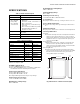
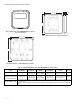
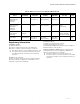

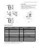
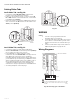


Table Of Contents

T10 PRO SMART THERMOSTAT WITH REDLINK
33-00462—01 8
Setting Slider Tabs
Set R Slider Tab, see Fig. 10.
• Use built-in jumper (R Slider Tab) to differentiate
between one or two transformer systems.
• If there is only one R wire, and it is connected to the R,
Rc, or RH terminal on the old thermostat, set the slider
to the up position (1 wire).
• If there is one wire connected to the R terminal and one
wire connected to the Rc terminal, set the slider to the
down position (2 wires).
Fig. 10.
Set U Slider Tab, see Fig. 11.
• Use built-in jumper (U Slider Tab) for IAQ device.
•When the U Slider Tab is in the down position (2 wires)
the U contacts are a dry set of contacts.
• If your IAQ device is powered by the cooling
transformer, move the U Slider Tab to the up position (1
wire). When this is done, the lower U terminal is
internally jumped to the Rc terminal. In this application,
you would hook up one wire from your IAQ device to the
upper U terminal and the other to the common side of
the cooling transformer. The 1 wire setting is most
commonly used when using a fresh air damper for
ventilation or using low speed fan for dehumidification.
• See wiring examples on the next page.
Fig. 11.
WIRING
NOTES:
1. Use 18- to 22- gauge thermostat wire.
Shielded cable is not required.
2. Set the R Slider Tab on the UWP to the up posi-
tion (1 wire) for 1 transformer systems or the
down position (2 wires) for 2 transformer sys-
tems.
3. Set the U Slider Tab to the position shown for
IAQ wiring diagrams on pages 12-13.
Wiring Diagrams
Fig. 12. Heat only: gas or oil furnace.
9
M37789
M37790
W R
G
C
S
S
Y
Y2
G
C
U
U
A
W2
W
K
Rc
R
L/A
E
AUX
M37813
1
COMMON REQUIRED.
G USED FOR INDEPENDENT FAN CONTROL ONLY. MOST HEAT
ONLY, GAS OR OIL FORCED AIR SYSTEMS DO NOT USE A FAN
(G) WIRE.
2
1
2
FURNACE
R/Rc
SWITCH UP
O/B
HEAT ONLY.
GAS OR OIL FURNACE.