
T10 Pro Installation Manual


7
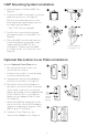
Heat pumps systems
1H/1C Heat Pump System
R Power
Rc [R+Rc joined by Slider Tab]
Y Compressor contactor
C 24VAC common
O/B Changeover valve
G Fan relay
2H/1C Heat Pump System
R Power
Rc [R+Rc joined by Slider Tab]
Y Compressor contactor
C 24VAC common
O/B Changeover valve
G Fan relay
Aux Auxiliary heat*
E Emergency heat relay*
L Heat pump fault input
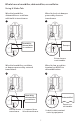
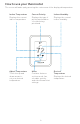
2H/2C Heat Pump System
R Power
Rc [R+Rc joined by Slider Tab]
Y Compressor contactor (stage 1)
C 24VAC common
O/B Changeover valve
G Fan relay
Y2 Compressor contactor (stage 2)
L Heat pump fault input
3H/2C Heat Pump System
R Power
Rc [R+Rc joined by Slider Tab]
Y Compressor contactor (stage 1)
C 24VAC common
O/B Changeover valve
G Fan relay
Aux Auxiliary heat*
E Emergency heat relay*
Y2 Compressor contactor (stage 2)
L Heat pump fault input
* If you do not have separate wires for the Aux and E terminals, connect the wire to the Aux terminal.
NOTE: Do NOT use W for heat pump applications. Auxiliary heat must wire to AUX or E.